

Wire Harness vs PCB — When to Use Each in Your Product
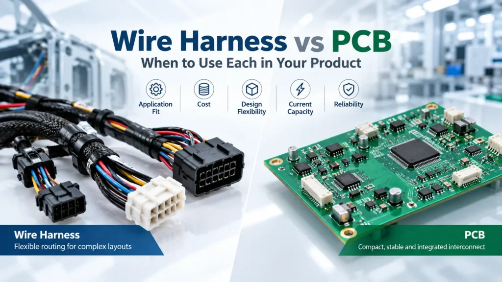
Wire Harness vs PCB — Core Difference
Wire harnesses connect separated parts using wires or cables, often grouped into branches. PCBs provide fixed copper paths for compact, repeatable connections. Choose between them based on physical layout, electrical load, movement, service access, and production needs. Many products work best with both.
A wire harness does not replace the electronics on a board. A bare PCB provides interconnects and mounting features; a populated board is a PCBA. A PCB backplane can also connect several modules, so board-based interconnects are not limited to one assembly.
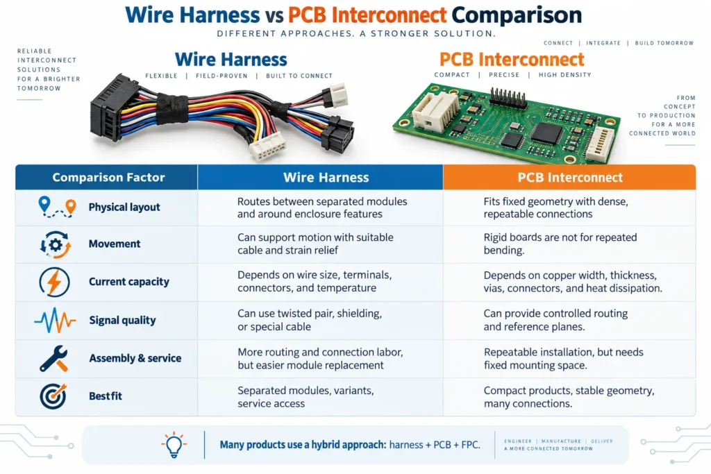
The table below mainly compares harnesses with rigid PCBs. Flexible printed circuits, or FPCs, are another printed-circuit option, discussed later.
| Factor | Wire Harness | PCB |
|---|---|---|
| Physical layout | Routes between separated modules and around enclosure features. | Fits fixed geometry with dense, repeatable connections. |
| Movement | Can support motion when cable, routing, and strain relief suit the duty. | Rigid boards are not designed for repeated bending; FPC needs separate evaluation. |
| Current capacity | Depends on wire size, terminals, connectors, and installed temperature. | Depends on copper geometry, vias, connectors, and heat dissipation. |
| Signal quality | May use suitable twisted pairs, shielding, or controlled-impedance cable. | Can provide controlled routing and reference planes when designed correctly. |
| Assembly work | Includes cutting, termination, routing, securing, and connection checks. | Includes fabrication, any component assembly, testing, and installation. |
| Service access | Detachable branches can support module replacement. | Replacement depends on board boundaries and connector access. |
| Cost | Varies with wire count, connectors, tooling, labor, and tests. | Varies with board construction, components, tooling, volume, and tests. |
When Wire Harnesses Are the Better Choice
Use a harness when connections must reach different locations inside a product. Examples include a controller linked to door-mounted switches, remote sensors, fans, or a power supply. Branch lengths can follow the enclosure rather than forcing every connection onto one board.
Harnesses can also suit products with several mechanical variants. A revised branch may accommodate a moved connector without redesigning the main PCBA. That change still needs drawing control and electrical verification.
Service access matters too. A technician may need to disconnect a pump or display without replacing the controller. Plan accessible connectors, clear identification, and enough space for removal.
Flexibility alone does not guarantee durability. TE Connectivity’s wire protection guidance highlights abrasion, heat, moisture, and strain relief. Define supports and bend paths so moving wires do not rub against sharp edges or pull on terminals. Repeated motion requires cable construction suited to that motion.
When a PCB Interconnect Makes More Sense
A PCB interconnect suits stable geometry and many connections in a small area. It can organize routing between mounted connectors, controls, and electronic components. A backplane may also simplify connections between plug-in modules.
PCB interconnect design can reduce individual point-to-point wires. However, a board still needs mounting space, connector clearance, and a practical assembly sequence. Replacing every wire with a large board can make enclosure tolerances or service access harder to manage.
Signal requirements can influence the choice, but neither option guarantees good performance. Texas Instruments explains differential pairs in both PCB traces and cables. The complete signal path needs suitable impedance, loss, and timing. An ordinary unshielded harness is not equivalent to a purpose-designed high-speed cable.
Choose board-based routing where its fixed structure solves a real packaging or electrical problem. Confirm connector mating alignment and mechanical tolerances before freezing the layout.
Current Capacity and Power Handling Comparison
A harness does not automatically carry more current than a PCB trace. Larger wires may suit a power connection, while wider or thicker PCB copper may suit another design. Compare the actual path, not the technology name.
For a harness, check conductor size, length, insulation temperature limits, bundle conditions, terminals, and connectors. For a PCB, check copper width and thickness, vias, neck-downs, and heat dissipation. IPC-2152’s conductor-sizing guidance relates PCB current capacity to acceptable temperature rise.
The connector can limit either option. For example, Molex’s Micro-Lock Plus specification shows current derating for different wire sizes and numbers of powered circuits. Those ratings apply to that connector family, not every harness.
Check continuous and peak loads, voltage drop, and the highest expected enclosure temperature. Voltage rating and insulation spacing are separate checks; a suitable current rating does not prove electrical safety. Validate the assembled path under representative operating conditions.
Cost and Assembly Time Differences
A cost comparison between a cable harness and a circuit board should include the finished assembly, not just wire or bare-board prices. Both approaches can require engineering, tooling, fixtures, and inspection.
A simple harness may avoid a new board design for a low-volume project. Yet many branches, custom terminations, or difficult routing can add labor. Cutting and crimping may be automated, but enclosure installation and connection checks still need planning.
A PCB may simplify repeated installation once its design is stable. Its total cost can include fabrication, connectors, component assembly, testing, and scrap. Larger volumes may spread setup costs, but they do not make a PCB the cheaper choice in every case.
Compare both options using the same quantity, electrical requirements, test coverage, and service expectations. Include the time to fit parts into the enclosure. During box build assembly, access to screws, connectors, and cable clips can change the installation sequence.
Hybrid Approach — Combining Harnesses with FPC and PCB
A hybrid design gives each interconnect a specific job. For example, an industrial controller might use a rigid PCBA for control electronics, an FPC for a compact display connection, and a harness for remote sensors.
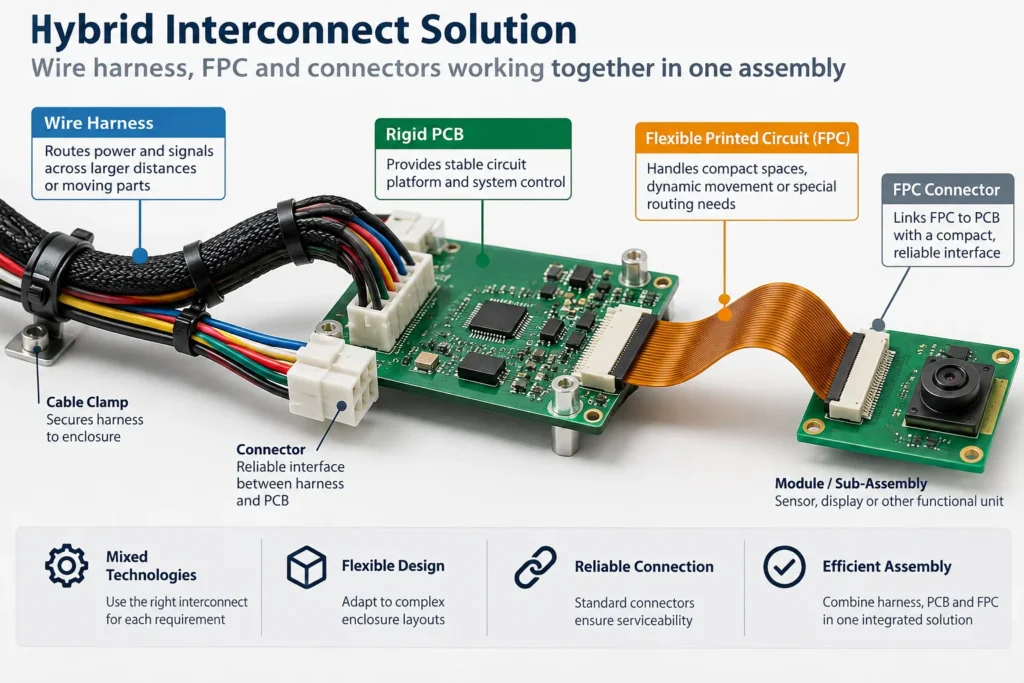
FPC can help when a thin connection must follow a defined three-dimensional path. Rigid-flex combines rigid and flexible regions in one circuit structure. Neither is a universal substitute for branched wiring. The FPC vs rigid PCB comparison explains the board-level differences.
Distinguish bending during installation from repeated movement in service. The Würth Elektronik flex design guide treats bend radius, cycle count, bending frequency, and stackup as design inputs. “Flexible” alone does not establish a service life.
Before choosing the mix, document:
- Where each connection starts and ends, including branch lengths and available space.
- Power loads, signal interfaces, grounding, and shielding requirements.
- Whether each section stays fixed, bends during assembly, or moves repeatedly.
- Connector access, retention, strain relief, and replacement needs.
- Required continuity, insulation, functional, and mechanical checks.
Review the interfaces together. A correctly built harness can still fail system requirements if its pinout, connector orientation, or shielding termination does not match the PCBA.
FAQ
Is a wire harness cheaper than a PCB?
Sometimes, especially for a simple connection or small build, but there is no universal winner. Compare engineering, connectors, tooling, assembly, testing, and installation costs. Use equivalent requirements and realistic quantities rather than comparing wire cost with bare-PCB cost.
Can a wire harness carry more current than a PCB trace?
It can, depending on the chosen wire and trace. Current capacity also depends on terminals, connectors, copper transitions, temperature rise, and cooling. Check the complete path and voltage drop. Do not infer a rating from wire size or PCB copper thickness alone.
When should I use FPC instead of a wire harness?
Consider FPC for a thin, compact interconnect with a defined route. Verify the electrical load, connector design, bend radius, and motion duty. Repeated bending requires a suitable flex design and validation. Branching, service access, or difficult motion may still favor a harness.
Does Benlida provide both wire harness and PCB assembly?
Benlida’s website lists wire harness assembly services alongside PCB fabrication and PCB assembly. Confirm your project’s scope, materials, manufacturing responsibilities, and testing during quotation. Ask which operations and records are included before placing an order.
Not Sure Which Interconnect Fits Your Product?
Share your enclosure layout, connection map, current and voltage requirements, signal types, motion conditions, and expected quantities with Benlida. Include available harness drawings, connector part numbers, and PCB or assembly files. Ask which interconnect options and validation scope can be supported for your project.