

FR-4 PCB Board Manufacturer
Custom FR-4 PCB Manufacturing
Custom FR-4 PCB boards with superior mechanical strength, stable dielectric performance, and reliable quality for industrial and electronic applications.
Request an FR-4 PCB Quote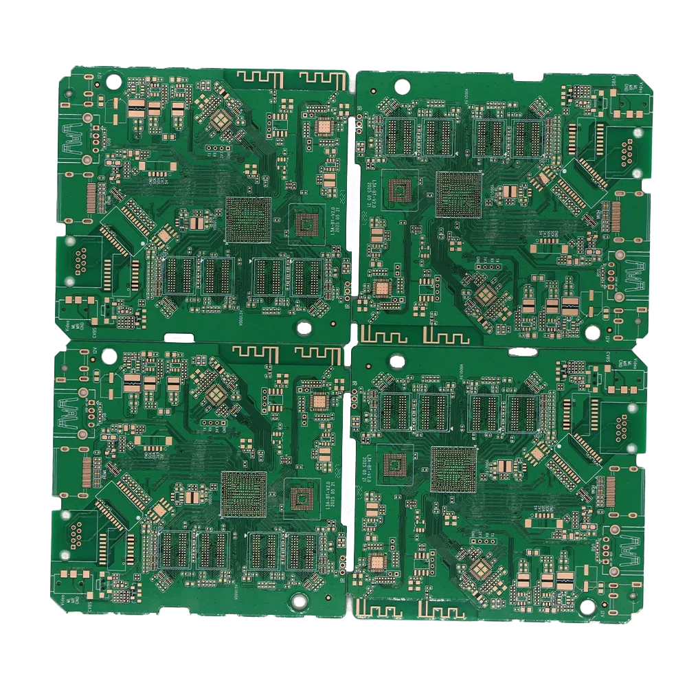
Thermal Stability: Good heat resistance
Dielectric Constant: Typically 4.2–4.8
Mechanical Strength: High rigidity
What Is FR-4?
FR-4 is a family of flame-retardant, glass-reinforced epoxy laminate systems commonly used for rigid printed circuit boards. It is not a single material with fixed Tg, Dk, Df or thermal performance. These properties vary with the supplier, laminate grade, resin content, glass style, thickness and test method; Dk and Df also depend on test frequency. For a PCB project, select the actual laminate grade and stack-up according to the operating environment, lead-free assembly profile, impedance requirements, reliability targets and compliance needs. State the required laminate grade and any substitution restrictions in the RFQ.
Our FR-4 PCB Manufacturing Capabilities
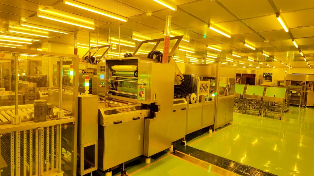
We offer at Benlida highly reliable solutions for manufacturing FR-4 circuit boards with advanced manufacturing capabilities to manufacture from 1 to 32-layer printed circuit boards with impedance control, fine-line process, and various surface finishes.Through stringent quality management and expert engineering, we assure you high-performance FR4 PCB boards for different purposes, including prototyping and mass production.
Related services and board types: Explore our PCB Manufacturing Services or compare Multilayer PCB options.
Layer Count
1-32 layers
Impedance Requirement
Target and tolerance required in the RFQ
Min Board Size
3×3 mm
Inner Copper Thickness
1-2 oz (up to 4.5 oz for 2-layer)
Surface Finish
HASL, Lead-free HASL, ENIG
Hole Tolerance
Plated: +0.13/-0.08 mm; Non-plated: ±0.2 mm
Min Plated Slot
0.5 mm
Min BGA Pad
0.20 mm
Verification Requirement
Specify coupon, TDR and report needs in the RFQ
Max Board Size
Up to 1200 × 600 mm
Outer Copper Thickness
1-2 oz (up to 4.5 oz for 2-layer)
Gold Finger Bevel
Supported
Min Via Size
0.15 mm (hole) / 0.25 mm (pad)
Min Track Width/Spacing
4/4 mil (0.10/0.10 mm)
Min Non-Plated Slot
1.0 mm
Backdrill
Supported (≥4 layers)
FR-4 PCB Material Selection Guide
FR-4 is a family of glass-reinforced epoxy laminate systems, not a single material grade. Grades differ in formulation, glass-transition temperature (Tg), thermal behavior, and other properties. Select the laminate grade according to the assembly profile, operating environment, electrical requirements, reliability needs, and compliance requirements.
Common FR-4 Laminate Categories
| FR-4 Material Type | Typical Tg Value | Key Characteristics | Recommended Applications |
|---|---|---|---|
| Standard FR-4 | 130–150℃ | Relatively inexpensive material with sufficient mechanical strength and electrical insulation properties and stable processing properties | Consumer electronics, general control boards, home appliances |
| Mid-Tg FR-4 | 150–170℃ | Improved thermal resistance and dimensional stability compared with standard FR-4 | Industrial controls, communication equipment, automotive electronics |
| High-Tg FR-4 | 170–200℃ | Improved heat resistance and low thermal expansion | Automotive components, industrial machinery, reliable electronics |
| Ultra High-Tg FR-4 | ≥200℃ | Designed for demanding thermal environments with excellent heat resistance and long-term stability | Aerospace, energy systems, advanced industrial applications |
| Halogen-Free FR-4 | 150–180℃ | Environmentally friendly laminate with reduced halogen content while maintaining reliable electrical and mechanical properties | New energy products, green electronics, export-oriented applications |
Multilayer Stack-Up and Controlled Impedance
For multilayer FR-4 PCBs, the layer stack and controlled-impedance requirements should be reviewed together before fabrication. Characteristic impedance depends on transmission-line geometry and the selected construction, including trace width and finished copper thickness, dielectric thickness and Dk, differential-pair spacing, reference-plane assignment and, for surface traces, solder mask.
For quotation review, include Gerber or ODB++, NC Drill files, the proposed stack-up or layer assignment, finished board thickness, copper requirements, and a fabrication drawing or impedance table.
Impedance Targets
State whether each structure is single-ended or differential. Provide the target impedance, acceptable tolerance and routing layer.
Signal and Reference Layers
Identify the reference plane for each controlled structure and include the proposed layer assignment and finished board thickness.
Material and Geometry Inputs
Provide copper requirements, trace width, differential spacing and any specified laminate grade. Use grade- and construction-specific Dk data instead of one generic FR-4 value.
Verification Requirements
If a coupon, TDR measurement or impedance report is required, state the method, acceptance criteria and documentation requirement in the RFQ. Availability and the final test plan must be confirmed for the order.
For deeper design guidance, read the PCB Stack-Up Design Guide. See Multilayer PCB Manufacturing for general multilayer fabrication. For RF/microwave or low-loss material projects, see High-Frequency PCB Manufacturing.
Why Choose Our FR-4 PCB?
Because of years of experience in PCB fabrication, Benlida offers dependable FR-4 PCB fabrication services for various electronics applications. We pay special attention to all details, starting from materials and fabrication process to the final inspection, to guarantee the stable operation and consistent quality.
High-Quality FR-4 Material
We choose highly reliable FR-4 materials with different Tg values according to application requirements that include general electronics, industrial applications, and high-reliability products.
Advanced Manufacturing Capability
With support for 1–32 layer production, our manufacturing capabilities include precise circuit fabrication, controlled impedance, microvia processing, and multiple surface finishes, providing dependable FR4 PCB Board solutions for complex designs.
Strict Quality Control
Every FR-4 PCB goes through careful inspection and testing throughout the manufacturing process, ensuring stable electrical performance, dimensional accuracy, and long-term reliability.
Flexible Production Support
In addition to prototyping, Benlida provides tailored FR4 PCB Board production services for projects that require unique specifications.
Types of FR-4 PCBs
Benlida offers a wide range of FR-4 PCB options, including standard, High Tg, high-frequency, multilayer, and HDI designs, to meet different performance and application requirements. Each FR4 PCB Board is manufactured with reliable materials and precise processes to ensure stable performance for various electronic products.
Standard FR-4 PCB
Reliable and cost-effective, ideal for general electronic devices and everyday applications with high quality.
High Tg FR-4 PCB
Designed for high-temperature environments, offering enhanced thermal stability and mechanical performance.
High-Frequency FR-4 PCB
Optimized for fast signal transmission and reduced loss in RF and high-speed applications.
Multilayer FR-4 PCB
Multiple layers enable compact, complex circuits for advanced electronics and high-density designs.
HDI FR-4 PCB
High-density interconnect PCB for miniaturized devices with fine lines and microvias to match your demand.
FR-4 PCB Manufacturing Process and Key Controls
The manufacturing route differs between double-sided and multilayer boards. The outlines below show typical high-level stages for double-sided plated-through-hole (PTH) and conventional multilayer PTH FR-4 boards, not complete production travelers or work instructions. The actual sequence and applicable controls depend on the submitted and confirmed fabrication data, board construction and project requirements.
Key project controls to confirm for each order include material and construction, hole and metallization requirements, copper and critical geometry, surface finish and profile, and bare-board test and acceptance requirements.
Typical Double-Sided PTH FR-4 Process
- 1 DFM/CAM and Material Review Review Gerber or ODB++, drill data, fabrication drawing, material and order requirements.
- 2 Material Preparation and Drilling Prepare the selected laminate and drill the required holes.
- 3 Hole-Wall Preparation and Metallization Prepare the drilled hole walls as required and form plated connections using the confirmed process route.
- 4 Outer-Layer Imaging, Plating and Etching Form the outer circuitry and inspect it at the applicable control point.
- 5 Solder Mask, Legend and Surface Finish Apply the specified solder mask, markings and surface finish.
- 6 Profiling and Bare-Board Electrical Test Complete the board outline and perform bare-board electrical testing according to the agreed order test plan.
- 7 Final Inspection and Packaging Complete applicable dimensional, workmanship and packaging checks before shipment.
Typical Conventional Multilayer PTH FR-4 Process
- 1 DFM/CAM, Material and Stack-Up Review Review the fabrication data, material construction, stack-up, layer assignments and order requirements.
- 2 Inner-Layer Imaging, Etching and Inspection Form and inspect inner-layer circuitry before lamination.
- 3 Bonding Treatment, Lay-Up and Lamination Prepare, align and laminate the confirmed multilayer construction.
- 4 Drilling, Hole-Wall Preparation and Metallization Drill the laminated panel, prepare the drilled hole walls as required and form plated connections using the confirmed process route.
- 5 Outer-Layer Imaging, Plating, Etching and Inspection Form and inspect the outer-layer circuitry at the applicable control point.
- 6 Solder Mask, Legend, Surface Finish and Profiling Apply the specified solder mask, markings and surface finish, then complete the board outline.
- 7 Bare-Board Electrical Test, Final Inspection and Packaging Perform bare-board electrical testing according to the agreed order test plan, followed by applicable final checks and packaging.
These routes cover typical conventional PTH constructions. HDI PCB manufacturing, sequential lamination, blind or buried vias, via filling, backdrilling and other special constructions require a separate process review. The metallization, plating and etching sequence, and the order of surface finish, marking, profiling and electrical test, can vary with the selected material and finish, panel flow and confirmed manufacturing route.
FR-4 PCB Surface Finish
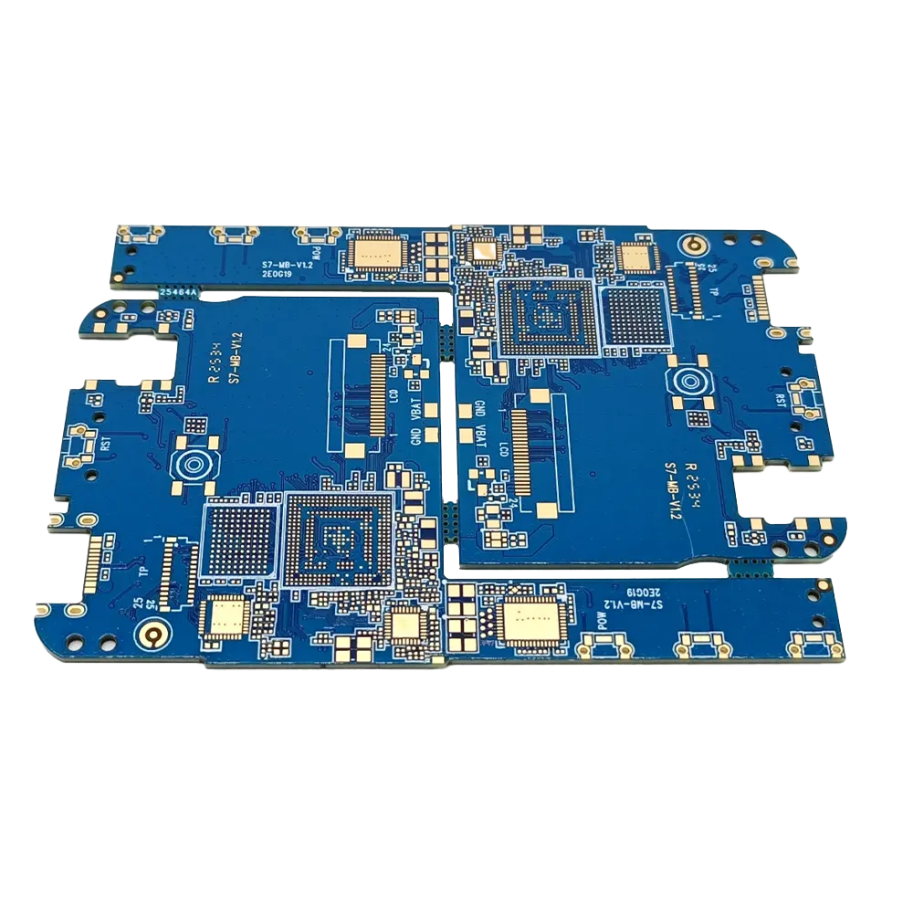
Benlida can offer several choices for FR-4 PCB surface finishes, such as HASL, Lead Free HASL, ENIG, Immersion Tin, Immersion Silver, and OSP, which will suit different assembly requirements and application purposes. Every surface treatment of FR4 PCB Board is chosen in order to guarantee better solderability and protection.
HASL
A traditional, cost-effective finish using molten solder, ideal for general-purpose PCBs.
Lead-Free HASL
Environmentally friendly version of HASL, meeting RoHS standards for lead-free electronics.
ENIG
Provides a flat, gold-coated surface for excellent solderability and reliable high-frequency performance.
Immersion Tin
Offers uniform, smooth surface with good solderability for short to medium-term applications.
Immersion Silver
Provides high conductivity and excellent surface planarity for precision assembly and fine-pitch parts.
OSP
Organic solderability preservative protects copper while remaining flat, perfect for fine-pitch components.
FR-4 and Alternative PCB Material Systems
These four options are not equivalent material grades. RO4350B is a specific laminate grade, FR-4 is a laminate family, an aluminum-based IMS is a board construction, and a polyimide flex system combines materials and construction. Compare them by project requirements and by data for the exact grade and stack-up—not by one generic Dk, Tg, thermal-conductivity or operating-temperature value.
RO4350B High-Frequency Laminate
Specific Grade
Comparison Level
A specific woven-glass-reinforced hydrocarbon/ceramic laminate grade.
Typically Considered When
Controlled loss, phase stability or RF/microwave performance is important and the grade fits the design.
Key Data to Verify
Core and bondply thickness, process and design Dk, Df, copper foil, project frequency, stack-up, hybrid compatibility and material availability.
Important Boundary
RO4350B is one specific Rogers material. Its data must not be extended to every Rogers material, and availability requires quotation review.
FR-4 Laminate System
Laminate Family
Comparison Level
A family of glass-reinforced epoxy laminates and prepregs used mainly in rigid PCB constructions.
Typically Considered When
The selected grade meets the project’s electrical, thermal, assembly and reliability requirements.
Key Data to Verify
Supplier and grade, Tg test method, Td, Z-axis expansion, Dk/Df conditions, glass style, resin content, stack-up and availability.
Important Boundary
FR-4 has no single universal Dk, Tg, CTE, thermal conductivity or continuous-use temperature.
Aluminum-Based IMS
Board Construction
Comparison Level
A rigid construction with copper circuitry, an electrically insulating thermally conductive dielectric layer and an aluminum base.
Typically Considered When
The design needs a managed heat path through an insulating layer to a metal base, often in power or LED applications.
Key Data to Verify
Dielectric thickness, thermal impedance and conductivity, withstand voltage, copper construction, aluminum alloy and thickness, interface material and heat sink.
Important Boundary
Metal or dielectric thermal conductivity alone does not describe complete PCB thermal performance. IMS is not a direct substitute for every multilayer FR-4 design.
Polyimide Flex / Rigid-Flex System
Material System
Comparison Level
A material system combining polyimide laminate, copper, coverlay and any required adhesive or bondply for flex or rigid-flex circuits.
Typically Considered When
The circuit must bend during installation or service, or space and mechanical integration require a flex construction.
Key Data to Verify
Exact laminate, adhesive and coverlay system, bend radius and cycles, layer count, copper type, Dk/Df conditions, Tg method and environmental exposure.
Important Boundary
Polyimide does not automatically mean dynamic-flex capability or one universal temperature rating.
This comparison is a design-screening guide, not a material specification. Properties vary with the exact product grade, construction, thickness, copper foil, direction, frequency and test method. Confirm material availability, manufacturability and approved substitutions for each quotation.
For deeper material-selection guidance, read the Ceramic PCB vs FR-4 Material Comparison and the Rogers RO4350B PCB Material Guide.
FR-4 PCB Testing & Inspection
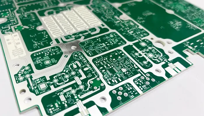
At Benlida, we implement strict quality control at all stages of the FR-4 PCB manufacturing process, including the design, production, and inspection processes. This ensures that every FR4 PCB Board is made up to specification.
Electrical Testing
Electrical testing is performed to verify circuit continuity and identify potential open or short circuit issues, ensuring reliable connections and stable performance of the FR-4 PCB.
Impedance Testing
For designs requiring controlled impedance, testing is carried out to confirm that the circuit performance meets the specified impedance requirements for reliable signal transmission.
Dimensional Inspection
It is ensured that critical factors, like board dimensions, hole sizes, and manufacturing tolerances, meet the standards of FR4 PCB Board by testing these aspects against the design specifications.
Surface Finish Inspection
Surface finish types, which include HASL, Lead-Free HASL, and ENIG, are tested to ensure good surface finish, solderability, and assembly requirements.
Manufacturing Process Inspection
Critical manufacturing processes like lamination, drilling, copper plating, and solder mask application are ensured to be consistent through the FR-4 PCB production process.
FR-4 PCB Manufacturing FAQs
Provide Gerber files with matching NC Drill files, or a complete ODB++ package. Include the design name and revision, quantity, board or panel size, layer count, finished thickness, copper requirement by layer, FR-4 grade or performance requirement, and surface finish. Add the fabrication drawing, stack-up, impedance targets and tolerances, testing or report requirements, and requested schedule when applicable.
No. FR-4 refers to a family of flame-retardant, glass-reinforced epoxy laminate systems used for rigid PCBs. Tg, Dk, Df, and other properties vary with the manufacturer, grade, resin content, glass style, thickness, frequency, and test method. Use the actual grade and datasheet for engineering decisions.
Do not select a laminate by Tg alone. Review the actual grade and Tg test method together with decomposition temperature, Z-axis expansion, assembly profile, operating environment, reliability needs, and any Dk, Df, or compliance requirements. If temperature is critical, specify the operating profile and applicable long-term thermal requirement; Tg is not a maximum continuous operating temperature.
State whether alternatives are allowed and which thermal, electrical, reliability, UL, or documentation requirements must match. If a manufacturer and grade are mandatory, state both in the fabrication package. Any proposed substitution should be identified and approved through the agreed order process before production.
Provide the target impedance and tolerance, whether each structure is single-ended or differential, the relevant nets, signal and reference layers, stack-up, copper and dielectric thicknesses, material or Dk at the relevant frequency, and any fixed trace width or pair spacing. State whether geometry may be adjusted and whether a test coupon, TDR measurement, or report is required. Feasibility and final verification must be confirmed for the order.
No. FR-4 is a laminate family, not an HDI process route or a low-loss performance rating. HDI features require a separate review of via structures and lamination cycles. High-speed or RF projects require review of frequency or rise time, interconnect length, loss budget, Dk and Df consistency, copper profile, and stack-up; a specific low-loss laminate may be needed.
Provide the layer count, finished thickness, copper requirement by layer, signal and plane assignment, impedance targets, material preference, and any thickness or registration limits. The quotation should confirm a specific material construction that is available and manufacturable for the submitted revision.
Define the required bare-board electrical, dimensional, workmanship, impedance, and project-specific verification. Include the applicable acceptance standard and revision, class or addendum when relevant, method, coverage or sampling, and required record or report. The final plan and deliverables must be confirmed for the order.
No. PCB fabrication and PCB assembly are separate scopes unless the quotation explicitly includes both. For PCB assembly services, also provide the BOM, pick-and-place or centroid data, assembly drawing, supply model, and any programming or functional-test requirements.
Key factors include the design revision, quantity, board or panel size, layer count, stack-up and material availability, thickness and copper, holes and slots, minimum features, surface finish, impedance, tolerances, testing or reports, panelization, and delivery destination. Price and schedule can be confirmed after the complete package and open engineering questions are reviewed.
FR-4 PCB RFQ Checklist
Prepare one revision-controlled fabrication package for each design. Use Gerber files with matching NC Drill files, or a complete ODB++ package. Add the project information below that applies to the order.
Core Quotation Information
- Gerber files with matching NC Drill files, or a complete ODB++ package
- Design name, revision, and quantity
- Finished board size or supplied panel size
- Layer count and finished board thickness
- Copper requirement by layer
- FR-4 manufacturer or grade, or the required material performance
- Surface finish
Add When Applicable
- Fabrication drawing with dimensions, tolerances, hole or slot details, and profile requirements
- Proposed stack-up and layer assignment
- Controlled-impedance targets, tolerances, and layer or net references
- Special structures or processes shown in the design
- Solder mask, legend, and panelization requirements
- Testing, inspection, acceptance-standard, and report requirements
- Material or compliance documents and substitution restrictions
- Requested schedule and delivery destination
- Revision and change history, when relevant
If the material or stack-up is still open, include the operating environment, assembly profile, impedance targets, and compliance needs that may affect selection. Use the form to request an FR-4 PCB quotation and confirm how the project files should be provided.
Why Choose Benlida for PCB Manufacturing?
Choose Benlida for precision PCB and PCBA manufacturing—delivering fast turnaround, consistent quality, and reliable performance from prototype to production.
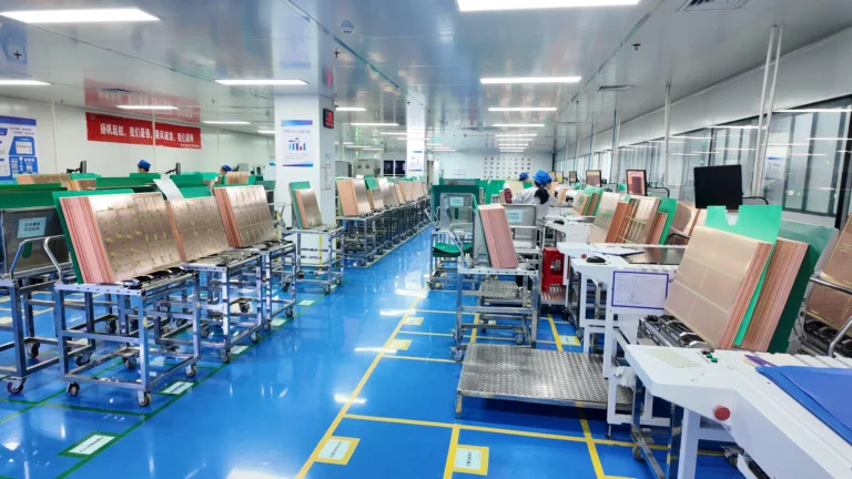
Experienced Manufacturing
PCB manufacturing experience since 2011. Authoritative manufacturing team delivering consistent quality at every scale.
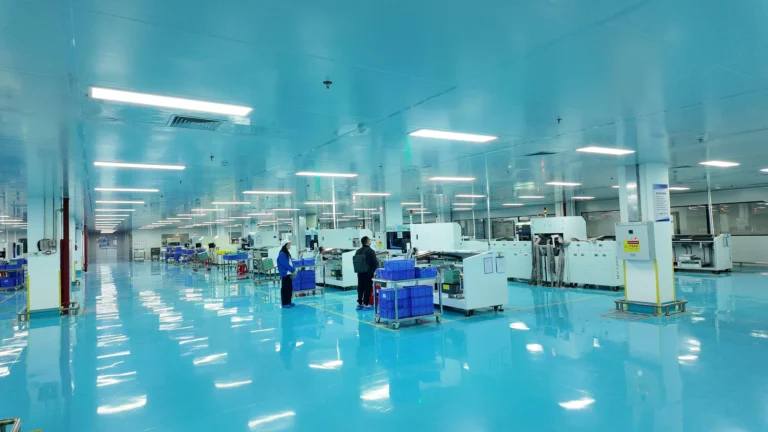
Advanced Quality Control
Comprehensive inspection processes including AOI, X-ray, and functional testing ensure every board meets the highest standards.
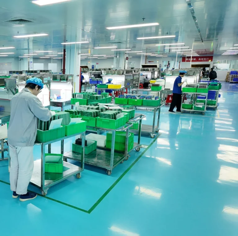
Fast Turnaround
Flexible production schedules with rapid prototype delivery. From design to finished PCB in record time without compromising quality.

Global Supply Chain
Trusted component sourcing from verified suppliers worldwide, ensuring authenticity and availability for every project.
Experienced Manufacturing
PCB manufacturing experience since 2011. Authoritative manufacturing team delivering consistent quality at every scale.
Advanced Quality Control
Comprehensive inspection processes including AOI, X-ray, and functional testing ensure every board meets the highest standards.
Fast Turnaround
Flexible production schedules with rapid prototype delivery. From design to finished PCB in record time without compromising quality.
Global Supply Chain
Trusted component sourcing from verified suppliers worldwide, ensuring authenticity and availability for every project.