

PCB Firmware Flashing – How It Works, Methods & Programming Standards
PCB firmware flashing loads software into a microcontroller, memory device, or other programmable part on an assembled circuit board. The code tells the hardware how to start, communicate, read sensors, control outputs, and perform its intended functions.
In PCBA production, embedded firmware flashing is more than copying a file. The manufacturer must use the correct version, voltage, interface, and sequence. The result must also be verified and recorded. A controlled process helps prevent dead boards, mixed firmware versions, and failures after shipment.
This guide explains the main programming methods, fixture needs, common risks, and the information a buyer should provide before production.
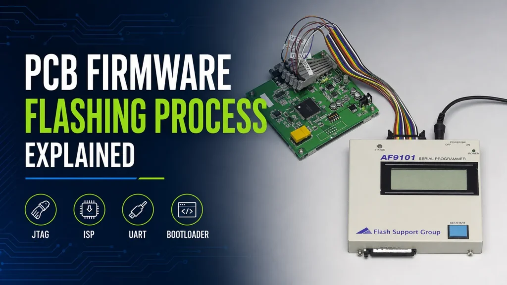
What Is PCB Firmware Flashing?
Firmware is software stored in non-volatile memory. It remains in the device after power is removed. Depending on the design, it may be stored inside an MCU, an external flash chip, an EEPROM, an FPGA configuration device, or another programmable component.
Firmware flashing is usually needed when a blank device is assembled on the PCB. It can also load the latest release or a customer-specific configuration. Other uses include serial numbers, calibration data, and rework.
A typical production process includes these steps:
- Confirm the PCB revision, target device, firmware file, and approved version.
- Connect the programmer through a header, cable, test pads, or fixture.
- Apply the correct power and place the device in programming mode.
- Erase the required memory area and write the firmware.
- Verify the programmed data by readback, checksum, CRC, or the tool’s verify function.
- Boot the board, run the agreed tests, and save the production result.
Verification matters. A programmer may report a successful data transfer, but the complete board can still fail. The cause may be a boot setting, wrong option byte, damaged interface, or assembly defect. For this reason, firmware loading is often followed by a functional testing service.
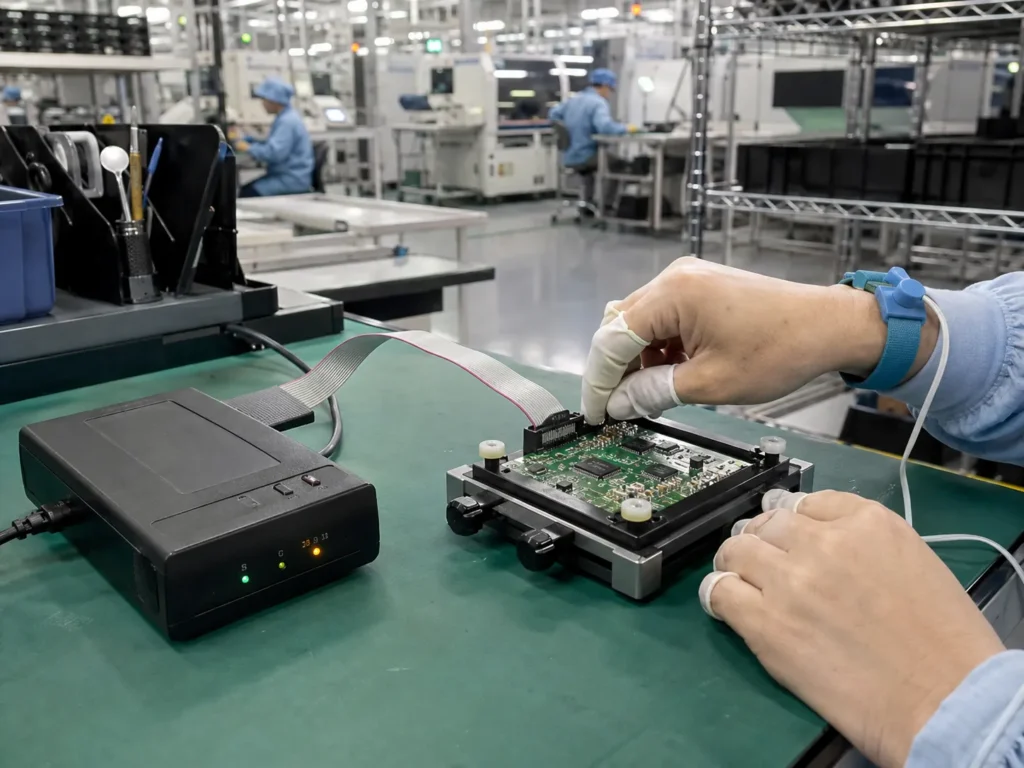
A production programmer connects to an assembled embedded board through a controlled interface or fixture.
Firmware Flashing Methods
When planning firmware programming for a PCB, start with the target component and its supported interface. The board must also provide safe electrical access. The following methods are common in PCBA production.
| Method | Typical access | Best use | Main advantages | Main limits |
|---|---|---|---|---|
| JTAG | TCK, TMS, TDI, TDO, reset, ground, and reference voltage | MCUs, processors, FPGAs, debug, and boundary-scan access | Good control, strong diagnostic access, and support for programming or configuration | Uses more signals and may need security controls after programming |
| ISP or ICSP | Device-specific clock, data, reset, power, and ground pins | Programming a mounted MCU or memory device | Simple, direct, and widely used for production fixtures | Pin names, voltage, and entry sequence vary by device family |
| UART bootloader | TX, RX, ground, boot control, and reset | Boards with a ROM or application bootloader | Low-cost equipment and few signal lines | Often slower and dependent on boot mode, baud rate, and protocol support |
| USB bootloader | D+, D-, VBUS, ground, boot control, and reset | Products that already expose a USB port | Convenient connection and useful for later updates | Enumeration, drivers, cable quality, and bootloader support can affect reliability |
JTAG uses a standardized test access architecture. IEEE 1149.1 covers test, programming, configuration, and debug access. Many Arm-based boards use the lower-pin-count SWD interface instead.
ISP is a general term, not a universal connector. Microchip’s ICSP documentation, for example, uses clock, data, reset, power, and ground connections. Follow the programming specification for the exact part.
Bootloader support also varies. STMicroelectronics’ STM32 system-memory bootloader guide lists interfaces such as USART, USB, I2C, SPI, and CAN. Confirm the MCU model and revision before fixture design.
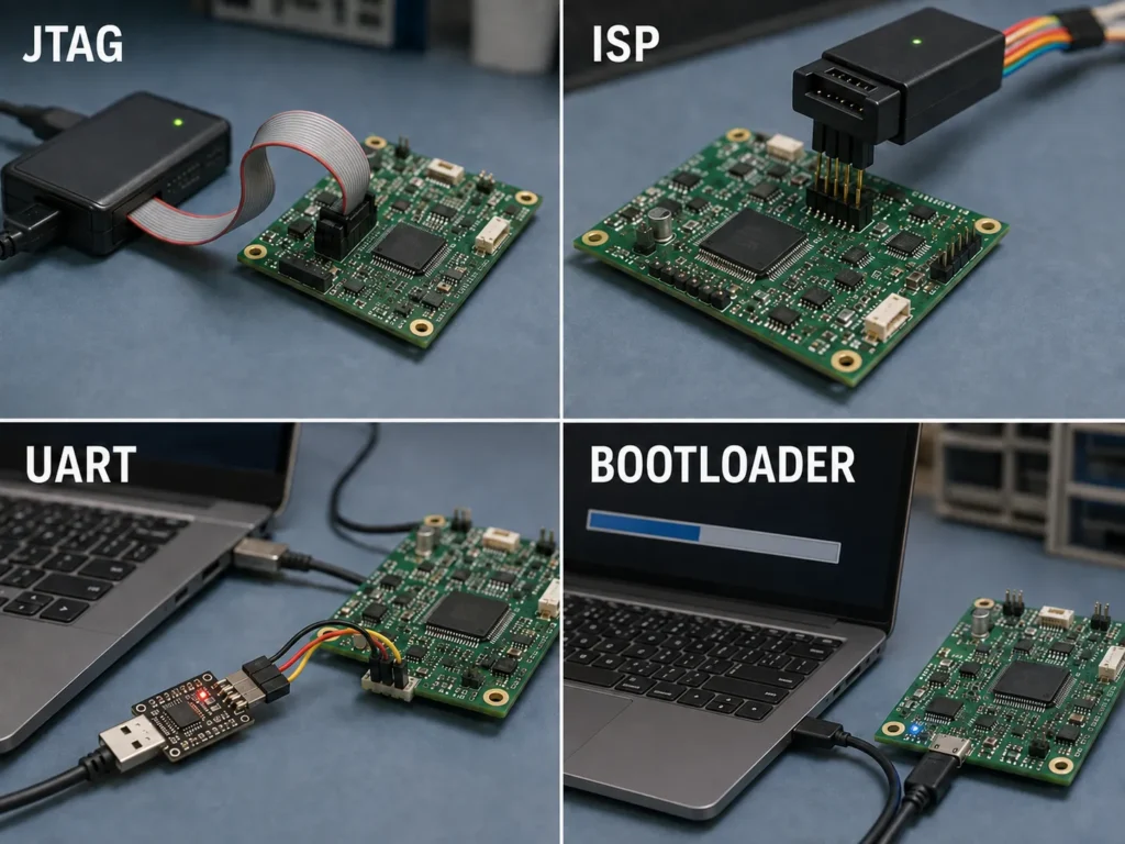
JTAG, ISP, UART, and USB bootloader methods use different signals, tools, and production workflows.
In-Circuit Programming vs. Post-Assembly Programming
These terms are not strict opposites. In-circuit means the device is programmed while mounted on the PCB. Post-assembly describes when it happens. Most PCBA projects use both.
Buyers normally choose between two production workflows:
Programming Integrated Into the Assembly or Test Line
Flashing is built into ICT or functional test. This reduces handling and can improve throughput. One system can record programming and test results. Fixture cost is higher, and design changes require tight control.
Programming at a Separate Post-Assembly Station
A standalone station suits prototypes and frequent firmware changes. It can be updated without changing the main test line. However, it adds handling and labor. Throughput may be lower.
Pre-programmed components can save line time. They also add inventory and version-control risk. Loading approved firmware after assembly often gives more flexibility.
Programming Fixtures and Test Points
A production fixture holds the PCB in a repeatable position. Pogo pins contact programming pads, power, ground, reset, and boot signals. This avoids repeatedly attaching a small connector.
Plan access before releasing the PCB layout. Review these points with the fixture designer and manufacturer:
- Provide accessible pads for every required programming signal.
- Include a solid ground connection and the target reference voltage.
- Make reset and boot-mode control available when the device requires them.
- Keep components, tall connectors, solder mask, and mechanical parts out of the probe area.
- Confirm pad size, spacing, finish, and access side with the fixture supplier.
- Prevent the programmer from back-powering other circuits through signal pins.
- Check whether shared pins need isolation resistors or other protection.
- Add clear board orientation and tooling features for repeatable alignment.
IPC-2221C gives generic printed-board design requirements. It does not set one pad size for every programming fixture. Geometry depends on the probe, board tolerance, and fixture. Record the agreed values in the manufacturing data.
Common Firmware Flashing Issues and How to Avoid Them
Wrong Voltage or Logic Level
A 3.3 V programmer can damage a 1.8 V target or fail to detect it. State which side supplies power. Define the voltage range and current limit.
Incorrect Reset, Boot, or Timing Sequence
Some devices need a specific reset pulse, boot level, clock speed, or delay. Put the sequence in the work instruction.
Signal Contention or Back-Powering
Another component may drive the programming line. A signal can also feed an unpowered rail. Review shared nets and the complete power state.
Poor Contact or Connector Damage
Dirty pads, worn pogo pins, weak pressure, and misalignment cause intermittent failures. Small headers can also wear out. Use a fixture for volume and replace contact parts on schedule.
Wrong File, Option Bytes, or Security Settings
A valid file can still be wrong for the PCB revision. Configuration bits can change the clock, boot source, or protection. Control the file, checksum, revision, and script together. Test locking on samples.
Programming Without a Functional Check
A verify result confirms memory under the tool’s rules. It does not prove that every peripheral works. Add a boot check and agreed functional tests.
What to Tell Your PCBA Manufacturer
A PCB firmware programming service needs a complete package before quotation or an engineering build. This lets the manufacturer confirm equipment, fixture cost, cycle time, security, and test coverage.
- Exact target component part number, package, and approved silicon revision.
- PCB revision and a programming pinout or connector drawing.
- Firmware file, file format, version, release date, and checksum.
- Required interface, programmer model, adapter, software, and script version.
- Power source, voltage, current limit, and required power-up sequence.
- Reset, boot-mode, erase, programming, and locking sequence.
- Option bytes, fuses, configuration words, and read-protection settings.
- Rules for serial numbers, MAC addresses, calibration data, or customer keys.
- Verification method, pass criteria, retry limit, and rework process.
- Required production log fields and the link between each result and board serial number.
For a one-stop project, confirm how firmware loading fits into turnkey PCB assembly, inspection, and final testing. Ask for a sample report before volume production. If firmware or keys are confidential, agree on transfer, access, storage, and deletion rules in writing.
Frequently Asked Questions
Can firmware be flashed after PCB assembly?
Yes. This is common in PCBA production. The mounted device can be programmed through JTAG, ISP, UART, USB, or another supported interface. The PCB must provide safe access to the required signals.
Which PCB firmware flashing method is best?
There is no best method for every board. JTAG offers broad access. ISP is direct and common. UART and USB bootloaders can use fewer connections. The right choice depends on the target device, board access, speed, security, and production volume.
What firmware file should I send to the manufacturer?
Send the production-approved format required by the programming tool, such as BIN, HEX, ELF, or a vendor-specific package. Include the version and checksum. Also send any option-byte, fuse, serial-number, or locking instructions.
How is successful firmware programming verified?
The programmer may use readback, byte comparison, checksum, CRC, or a device-specific verify command. A good process then boots the board and performs agreed functional checks. The result should be recorded against the unit or production lot.
Plan Firmware Flashing Before Production
Early planning reduces fixture changes, programming delays, and version mistakes. Benlida can review your files, programming interface, verification needs, and test plan as part of a PCB firmware flashing service.
Request firmware flashing quote and include the PCB revision, target device, firmware format, order quantity, and required test coverage.