

Rogers RO4350B PCB Material Guide — Specifications, Applications & Design Tips
Rogers RO4350B PCB material is widely used in RF, microwave, and high-speed designs. It offers low signal loss and stable electrical performance. It is also easier to process than many PTFE-based microwave laminates.
This guide explains the main RO4350B material properties. It also compares RO4350B with FR-4 and RO4003C. You will learn where the material works well and what to check before PCB fabrication.
Quick answer: Choose RO4350B when signal loss, impedance control, and high-frequency stability matter more than the lowest material cost. Standard FR-4 may still be a better choice for low-frequency circuits and cost-sensitive products.
What Is Rogers RO4350B?
RO4350B is a rigid, thermoset laminate from the RO4000 series. It uses woven glass reinforcement with a hydrocarbon and ceramic material system. It is not a PTFE laminate.
Rogers Corporation is a global engineered-materials company. Its Advanced Electronics Solutions business develops materials for high-frequency, high-speed, and high-power electronics. RO4350B is one of its best-known RF PCB laminate products.
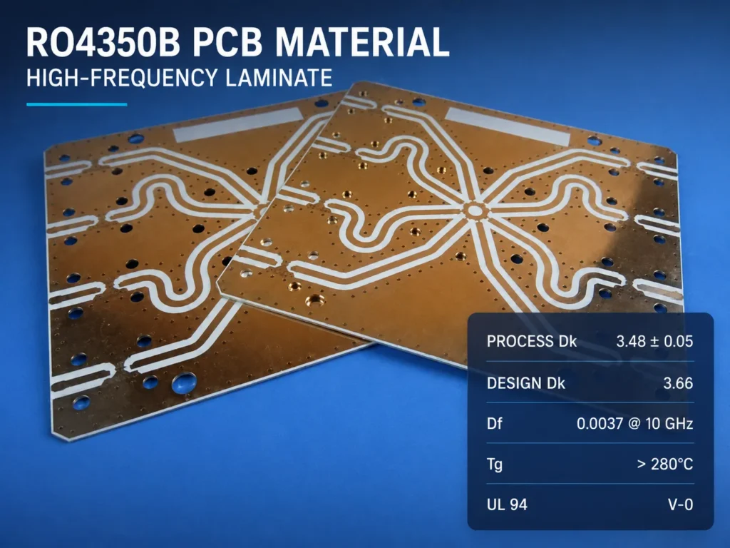
The material has a process dielectric constant of 3.48 ± 0.05 for most standard thicknesses. It also has a low dissipation factor of 0.0037 at 10 GHz. These properties help engineers predict impedance and reduce dielectric loss.
RO4350B can use many standard epoxy-glass fabrication processes. It does not need the sodium-etch hole treatment often associated with PTFE materials. It is also rated UL 94 V-0 and is compatible with lead-free processing. These features make it useful for RF products that need repeatable production.
Rogers RO4350B Key Specifications
The table below uses typical values from the official Rogers RO4000 series data sheet. Test methods and conditions matter. Use the current supplier data sheet when you build a simulation model or release a production stack-up.
| Property | Typical value | Why it matters |
|---|---|---|
| Material system | Woven glass reinforced hydrocarbon/ceramic | Supports rigid boards and FR-4-like processing |
| Process dielectric constant (Dk) | 3.48 ± 0.05 at 10 GHz and 23°C | Used for material quality control; the 0.004-inch laminate is an exception |
| Design dielectric constant | 3.66 from 8 to 40 GHz | A practical starting value for many circuit models |
| Dissipation factor (Df) | 0.0037 at 10 GHz; 0.0031 at 2.5 GHz | Lower Df helps reduce dielectric insertion loss |
| CTE, X/Y/Z axes | 10 / 12 / 32 ppm/°C from -55 to 288°C | Low Z-axis expansion supports plated-through-hole reliability |
| Glass transition temperature (Tg) | >280°C | Helps the laminate stay stable during thermal processing |
| Thermal conductivity | 0.69 W/(m·K) at 80°C | Helps move heat, but does not replace a complete thermal design |
| Standard dielectric thicknesses | 0.004, 0.0066, 0.010, 0.020, 0.030, and 0.060 in | Equal to about 0.10, 0.17, 0.25, 0.51, 0.76, and 1.52 mm |
| Standard copper cladding | 0.5 oz (18 µm) and 1 oz (35 µm) | Copper thickness changes trace geometry, loss, and etching limits |
| Flammability | UL 94 V-0 | Useful when the finished product requires a flame-rated laminate |
Important: The 0.004-inch RO4350B laminate has a process Dk of 3.33 ± 0.05. Other thicknesses use the typical 3.48 ± 0.05 value. Thickness availability, panel size, and copper options can also change. Confirm them before you finalize the PCB.
RO4350B vs FR-4: When to Choose Each
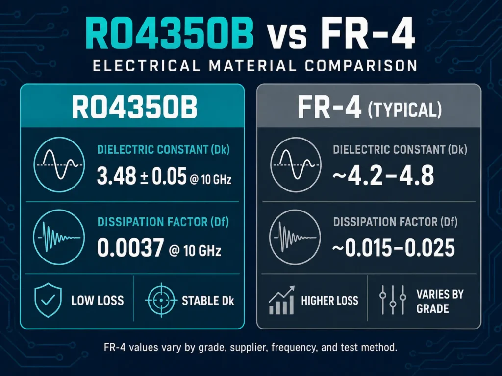
RO4350B and FR-4 serve different needs. RO4350B is a high frequency PCB material. FR-4 is a broad material category with many grades. Its electrical properties can vary by resin system, glass style, supplier, and test method.
| Factor | RO4350B | FR-4 |
|---|---|---|
| High-frequency loss | Low and well documented | Usually higher; depends on the exact grade |
| Dk control | Tight process Dk tolerance | Supplier and construction dependent |
| Impedance repeatability | Strong choice for RF and microwave lines | Suitable for many digital and lower-frequency designs |
| Fabrication | Uses many FR-4-like processes, with material-specific controls | Widely supported by PCB factories |
| Material cost | Higher | Lower for common grades |
| Best fit | RF, microwave, antennas, radar, and controlled-impedance networks | General electronics, power, control, and cost-sensitive products |
Choose RO4350B when loss budgets are tight or phase and impedance must stay consistent. Choose FR-4 when frequency is lower and cost is the main concern. A hybrid stack-up can use RO4350B only on critical RF layers. Other layers can use FR-4. This can lower cost, but the stack-up needs careful lamination and impedance planning.
Applications of Rogers RO4350B PCB
RO4350B is used when ordinary laminate loss or Dk variation can affect system performance. Common applications include the following.
5G and Wireless Infrastructure
Base-station antennas, RF front ends, filters, and matching networks need controlled impedance. They also need repeatable phase behavior. RO4350B supports these needs across high-volume wireless products.
RF Power Amplifiers
Power-amplifier boards carry RF energy and generate heat. Low dielectric loss helps protect the RF efficiency budget. Stable dimensions also help keep matching networks close to the intended values.
Radar and Phased-Array Systems
Radar channels depend on predictable line length, phase, and insertion loss. RO4350B can support feed networks, RF modules, and antenna structures. The final choice must match the operating frequency and environmental limits.
Satellite Communication Equipment
RO4000 materials are used in circuits such as low-noise blocks for direct-broadcast satellite systems. Low loss is valuable because received signals can be weak. The board must preserve signal quality before further processing.
Automotive Radar and Sensors
Automotive radar needs compact RF routing and stable electrical behavior. RO4350B may be used in radar and sensor modules. Engineers should also evaluate long-term temperature and oxidation exposure for the exact vehicle environment.
For support with prototypes or production, review Benlida’s high frequency PCB manufacturing capabilities.
Design Tips for Rogers RO4350B PCB
1. Use the Correct Dk in Your Model
Do not treat every Dk number as interchangeable. The process Dk is measured with a material test method. The design Dk is derived from circuit testing. Rogers lists 3.66 as the typical design Dk for common RO4350B constructions.
Use that value as a starting point, not a universal guarantee. Copper type, laminate thickness, glass weave, and transmission-line structure can change the effective result. Ask the PCB manufacturer which value is used in its impedance model.
2. Lock the Controlled-Impedance Stack-Up Early
Set the dielectric thickness, copper thickness, reference plane, and trace geometry before routing is complete. Include the finished copper thickness after plating. Include solder mask when it covers the RF trace.
Use a field solver for critical lines. Add impedance coupons when required. The fabricator can then measure the coupon and adjust production controls.
3. Keep RF Vias Short
Long via stubs can create unwanted resonance. They can also increase reflection. Use blind vias or back drilling when the frequency and stack-up justify the added cost. Place ground vias near RF transitions and connector launches. This gives return current a short path.
RO4350B does not require special sodium treatment before hole metallization. Still, drilling needs the correct carbide tools and process settings. The ceramic filler can increase drill wear.
4. Select Copper Weight with Impedance in Mind
Rogers lists 0.5 oz and 1 oz electrodeposited copper as standard options. Thicker copper can carry more current, but it also changes the impedance geometry. It can make fine-line etching more difficult.
For low-loss designs, also review copper surface roughness. Rough copper can increase conductor loss as frequency rises. LoPro foil may reduce insertion loss, but it changes material configuration and may affect qualification. Confirm the exact laminate code with the supplier.
5. Review Hybrid Stack-Ups Before Layout Release
A hybrid RO4350B and FR-4 construction can balance performance and cost. It also adds manufacturing choices. The bondply, press cycle, layer symmetry, and overall thickness must work together. Registration and resin flow need attention.
Send the proposed stack-up, target impedance, frequency range, copper weight, and via structure for an RF PCB DFM review. Early review can prevent an impedance redesign after the Gerber files are complete.
Rogers RO4350B vs RO4003C: What's the Difference?
RO4350B and RO4003C belong to the same RO4000 family. Both use a woven-glass-reinforced hydrocarbon and ceramic system. Both can use many standard FR-4 fabrication steps. Their electrical and flame-rating properties are different.
| Property | RO4350B | RO4003C |
|---|---|---|
| Process Dk at 10 GHz | 3.48 ± 0.05 | 3.38 ± 0.05 |
| Design Dk | 3.66 | 3.55 |
| Df at 10 GHz | 0.0037 | 0.0027 |
| Z-axis CTE | 32 ppm/°C | 46 ppm/°C |
| Thermal conductivity | 0.69 W/(m·K) | 0.71 W/(m·K) |
| UL 94 rating | V-0 | Non-flame-retardant standard construction |
RO4003C has lower Dk and lower Df. It may suit designs that prioritize lower dielectric loss. RO4350B offers UL 94 V-0 performance and lower Z-axis CTE. It may be the better fit when flame rating or plated-hole reliability is important. Neither material is always better. Select the laminate from the product requirements and the validated RF model.
Frequently Asked Questions
Is Rogers RO4350B better than FR-4?
RO4350B is usually better for RF and microwave circuits that need low loss and tight Dk control. FR-4 is usually more economical for lower-frequency and general electronic circuits. The right choice depends on frequency, loss budget, reliability, and cost.
What dielectric constant should I use for RO4350B?
Rogers lists a typical process Dk of 3.48 ± 0.05 and a typical design Dk of 3.66. Circuit simulation often starts with the design Dk. Confirm the value with your fabricator. The 0.004-inch laminate has a different process Dk.
Can RO4350B be processed like FR-4?
Many standard FR-4 processes can be used. These include imaging, etching, copper plating, and common final finishes. However, drill parameters, lamination materials, and surface preparation still need material-specific control.
What RO4350B thicknesses are available?
The Rogers data sheet lists standard thicknesses of 0.004, 0.0066, 0.010, 0.020, 0.030, and 0.060 inch. Other configurations may be available. Confirm current stock, tolerance, panel size, and copper cladding before ordering.
Can RO4350B and FR-4 be used in one multilayer PCB?
Yes. A hybrid stack-up can place RO4350B on critical RF layers and FR-4 on other layers. This can reduce material cost. The fabricator must review the bonding system, press cycle, thickness, registration, and impedance structure.
Plan Your Rogers RO4350B PCB Build
A successful RF board starts with a realistic stack-up. Share the operating frequency, target impedance, layer count, finished copper, via structure, surface finish, quantity, and test needs. These details help the manufacturer check material availability and fabrication risk.
Get Rogers RO4350B PCB quote from Benlida. Send your Gerber files, BOM, stack-up, and impedance requirements for review.