Zero-Defect FPC Manufacturing — Process Controls That Make It Possible
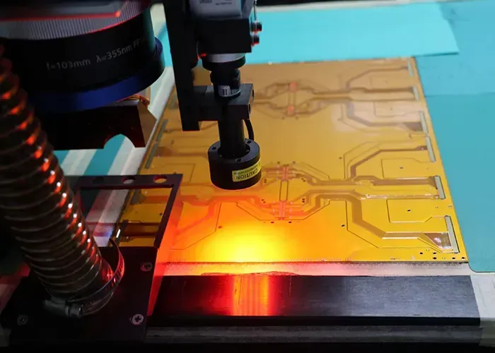
Can an FPC manufacturer deliver a batch with no defective boards? In real production, an absolute and permanent zero is difficult to guarantee. Flexible circuits use thin materials. They also pass through many sensitive processes. Small changes in heat, pressure, alignment, or handling can create defects.
However, zero-defect FPC manufacturing is still a practical quality goal. It means preventing defects instead of relying only on final inspection. It also means finding problems early, tracing their causes, and stopping the same issue from happening again.
For engineers and procurement teams, this approach reduces more than scrap. It lowers assembly risk, field failures, returns, and supplier-management costs. This guide explains the most common FPC defects, the controls used to prevent them, and the inspection methods that help reduce defect rates to near zero.
What Does Zero-Defect FPC Manufacturing Mean?
Zero defect FPC manufacturing does not mean that mistakes can never happen. It means that defects are not accepted as normal output. Each process must have a clear standard. Operators must react when a parameter moves out of range. Suspect material must not continue to the next step.
The goal is to make the board right the first time. This requires four connected actions:
- Prevent: Review the design and control materials before production starts.
- Detect: Inspect the product during production, not only at the end.
- Contain: Stop affected material before it reaches another process or the customer.
- Improve: Find the root cause and update the process to prevent repeat defects.
This matters because an FPC is often installed deep inside a product. Replacing a low-cost flex circuit may require disassembling an expensive device. A small defect can therefore create a much larger service cost.
The Most Common FPC Defects and Their Root Causes
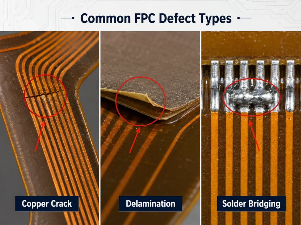
Flexible printed circuits fail in different ways from rigid PCBs. Thin copper and polyimide can bend, stretch, and move during production. The following defects are among the most common risks.
| Defect | Typical Root Causes | Main Prevention Method |
|---|---|---|
| Copper cracking | Bend radius is too small, copper grain direction is unsuitable, traces cross the bend area poorly, or repeated flexing exceeds the design limit. | Review bend zones, trace direction, copper type, stack-up, and expected flex cycles during DFM. |
| Delamination | Moisture, contamination, poor surface preparation, incorrect lamination temperature, uneven pressure, or incompatible materials. | Control material storage, cleaning, lamination recipes, pressure, temperature, and cure time. |
| Coverlay bubbles or misalignment | Trapped air, unstable alignment, incorrect adhesive flow, contamination, or poor lamination conditions. | Use controlled alignment, clean surfaces, verified tooling, and first-article checks. |
| Open circuits | Over-etching, damaged traces, poor plating, drilling errors, contamination, or cracks in narrow conductors. | Control imaging and etching, inspect copper patterns, and perform electrical testing. |
| Short circuits | Under-etching, copper residue, foreign material, plating bridges, or conductor spacing below process capability. | Set manufacturable spacing, control etching, and use AOI plus electrical testing. |
| Solder bridging after assembly | Excess solder paste, poor stencil design, pad spacing issues, component movement, or an unstable reflow profile. | Apply DFM and DFA review, control printing, verify placement, and inspect solder joints. |
| Pad lifting | Too much heat, weak adhesion, repeated rework, mechanical stress, or an unsuitable pad design. | Control thermal exposure, reinforce critical areas, and reduce unnecessary rework. |
| Via or hole defects | Drill wear, misregistration, debris, poor desmear, uneven plating, or a hole structure that exceeds process limits. | Check drill condition, registration, cleaning, plating thickness, and finished-hole requirements. |
Copper Cracking
Copper cracking is a major flexible PCB defect. It often begins in a bend area. The trace may work during initial testing but fail after installation or repeated movement. This makes bend-zone design important before fabrication starts.
The FPC drawing should state whether the bend is static or dynamic. It should also define the bend radius and expected cycle life. These details help the manufacturer choose suitable copper, materials, and process controls.
Delamination and Coverlay Problems
Delamination occurs when bonded layers separate. Coverlay bubbles are a related warning sign. Moisture, contamination, and poor lamination control can all reduce adhesion.
These defects may worsen during soldering, thermal cycling, or field use. Stable material and lamination controls are essential.
Open and Short Circuits
Open circuits break the intended electrical path. Short circuits connect conductors that should remain separate. Both defects can come from imaging, etching, drilling, plating, or handling problems.
Narrow traces and tight spacing require stable process capability.
Process Controls That Prevent FPC Defects
Final inspection is necessary, but it cannot create quality. Reliable FPC manufacturing quality begins before the first panel enters production.
Pre-Production DFM Review
A DFM review checks whether the design can be produced with stable yield. For FPCs, the review should cover the stack-up, copper thickness, trace width and spacing, bend areas, vias, stiffeners, coverlay openings, panel layout, and surface finish.
Vias, sharp trace corners, abrupt width changes, and rigid terminations can become stress points. Correcting them before production is faster than repairing them later.
Benlida provides a pre-production DFM review to identify manufacturability risks before fabrication.
Material Selection and Incoming Inspection
FPC performance depends on the material system. Polyimide, copper foil, adhesive, coverlay, stiffeners, and surface finishes must suit the application.
Selection should consider temperature, flex type, bend cycles, electrical needs, chemical exposure, and assembly heat. Incoming checks should verify material identity, thickness, condition, shelf life, and documentation. Defined storage rules reduce moisture and handling risks.
Imaging, Etching, and Drilling Control
Imaging and etching define the conductor pattern. Poor control may create narrow traces, copper residue, opens, or shorts. Process limits should be based on actual manufacturing capability.
Worn drill tools increase hole variation and roughness. Registration errors reduce the annular ring. Tool-life limits and first-article checks help stop these defects early.
Lamination and Coverlay Alignment
Lamination must balance heat, pressure, vacuum, and time. A stable recipe helps the adhesive flow correctly without creating excessive squeeze-out, voids, or weak bonding.
Coverlay openings must align with pads and other exposed areas. Tooling and optical alignment can improve accuracy. The first panel or first article should be checked before full production continues.
Plating and Surface-Finish Control
Plating creates electrical connections through holes and protects exposed copper. Uneven or insufficient plating can reduce reliability. The process should control cleaning, activation, bath condition, current density, time, and thickness.
The surface finish must match the assembly process and end use. The choice should be agreed during design and quotation.
In-Process Inspection and Traceability
Inspection should occur at important process gates. These gates may include first-article checks, copper-pattern inspection, drilling verification, coverlay alignment, plating checks, and final electrical testing.
Each lot should be traceable to materials, equipment, settings, operators, and inspection results. Trend monitoring can reveal drift before it becomes a defect.
Inspection Methods Used in Zero-Defect FPC Production
No single inspection method can find every defect. A zero-defect strategy combines methods based on the design, product risk, and customer requirements.
| Method | What It Can Detect | Main Limitation | Typical Use |
|---|---|---|---|
| AOI | Open traces, shorts, missing copper, pattern errors, spacing problems, and some surface defects. | Cannot confirm every hidden internal condition or electrical function. | Copper-pattern and finished-board inspection. |
| Electrical test | Continuity, opens, shorts, and incorrect net connections. | May not identify the physical cause or predict every future mechanical failure. | Final verification of the circuit network. |
| X-ray inspection | Hidden structures, internal alignment, some via issues, and hidden solder-joint conditions after assembly. | Higher cost and slower inspection than standard optical methods. | Complex structures, hidden features, and risk-based analysis. |
| Controlled-impedance test | Whether impedance coupons or specified traces meet the required range. | Only relevant when controlled impedance is part of the design. | High-speed and signal-sensitive FPC designs. |
| Pull or peel test | Bond strength, pad adhesion, or material adhesion under defined conditions. | May be destructive and is usually performed on samples or test coupons. | Qualification, process validation, or customer-specific requirements. |
| Microsection analysis | Plating thickness, hole-wall quality, internal registration, and layer construction. | Destructive and based on selected samples. | Process verification and failure analysis. |
| Visual inspection | Surface contamination, scratches, coverlay defects, finish problems, and workmanship issues. | Depends on clear criteria, lighting, magnification, and inspector consistency. | In-process and final appearance checks. |
AOI Versus X-Ray Inspection
AOI uses cameras and inspection software to compare visible features with defined criteria. It is fast and effective for conductor patterns and surface conditions.
X-ray inspection is useful when the feature is hidden. It can support analysis of internal structures and assembled joints that optical systems cannot see. It is not required for every simple FPC. The inspection plan should match the product risk.
Electrical and Reliability Testing
Electrical testing confirms that the finished circuit has the correct connections. It should be combined with mechanical and material checks when the application includes repeated flexing, high temperature, or strict reliability requirements.
For critical projects, buyers should define test conditions in the procurement documents. They should state the IPC class, installation use, bend cycles, impedance requirements, thermal exposure, and any special acceptance criteria.

How Benlida Approaches Zero-Defect FPC Manufacturing
Benlida treats zero defects as a continuous improvement target. The focus is to reduce variation, prevent escapes, and make quality data useful for the next production run.
The approach includes the following steps:
- Engineering review before production: Design files are checked for manufacturability and possible FPC risk points.
- Incoming material control: Materials are checked before they enter production.
- First-article verification: Key dimensions and process results are confirmed before full production continues.
- In-process control: Important stages are inspected so problems can be contained early.
- Final inspection: Finished products undergo defined inspections and testing before shipment.
- Corrective action: Defects are analyzed so the cause can be removed, not only repaired.
Benlida provides strict pre-shipment inspections and free DFM checks for PCB files and BOMs. Its FPC capability page also lists AOI, X-ray, and functional testing as available quality-control methods. Buyers can review the applicable inspection plan on Benlida’s PCB quality inspection page.
Buyers can reference IPC-6013E when defining FPC requirements for applicable projects. This specification covers qualification and performance requirements for flexible and rigid-flexible printed boards. The required class, board type, installation use, and customer-specific tests should be stated in the order documents.
An internal quality example in the existing Benlida article uses a 0.1% defect rate as a baseline. The purpose of the zero-defect system is not to present that number as “good enough.” It is to keep reducing defects through training, process control, inspection, and corrective action.
Buyers may request inspection reports, electrical-test results, impedance data, material certificates, first-article records, microsections, or reliability-test reports.
What Buyers Should Confirm Before Ordering an FPC
A clear technical package improves quality and delivery. Confirm these items before ordering:
- FPC type, layer count, finished thickness, and stack-up.
- Static or dynamic flex use and the expected bend cycles.
- Minimum bend radius and the exact bend-zone location.
- Copper type, copper thickness, and critical trace requirements.
- Coverlay, stiffener, adhesive, and surface-finish requirements.
- Controlled impedance values and tolerances, when required.
- IPC performance class and installation use.
- Electrical, mechanical, thermal, and reliability tests.
- Inspection report, certificate, and traceability needs.
- Packaging, storage, and shelf-life requirements.
Early communication helps identify conflicts before material is ordered. Review Benlida’s FPC manufacturing services or submit project files for engineering review.
Frequently Asked Questions About Zero-Defect FPC Manufacturing
What causes the most common FPC defects?
Common causes include a bend radius that is too small, poor material handling, unstable lamination, coverlay misalignment, over-etching, under-etching, drilling errors, contamination, weak plating control, and designs that exceed stable process capability. A DFM review helps identify many of these risks before production.
How is FPC quality measured and tested?
FPC quality can be checked through AOI, visual inspection, electrical testing, controlled-impedance testing, X-ray inspection, microsection analysis, dimensional checks, and mechanical or reliability tests. The correct combination depends on the design and application risk.
What is IPC-6013 and why does it matter for FPC quality?
IPC-6013 is a qualification and performance specification for flexible and rigid-flexible printed boards. It helps buyers and manufacturers define board types, performance classes, installation uses, acceptance requirements, and test expectations. The purchase documents should state the required revision and class.
Can FPC defects be detected after assembly?
Many defects can be found after assembly, but detection becomes more difficult and expensive. AOI can find visible assembly issues. X-ray can inspect hidden joints and structures. Functional testing can reveal electrical problems. Prevention and bare-board inspection are still better than finding the defect after assembly.
What is the difference between AOI and X-ray inspection for FPC?
AOI checks visible features with cameras and software. It is fast and suitable for conductor patterns, alignment, and surface defects. X-ray checks features hidden inside the board or under components. It is useful for complex structures and hidden solder joints, but it is slower and more expensive.
Work With an FPC Manufacturer That Takes Quality Seriously
At Benlida, FPC projects can include a pre-production DFM review and defined inspection steps based on the design. Send your files and quality requirements before production begins. Our engineering team will review the project and identify key manufacturing risks.

