Industrial Control PCB Design — Reliability, EMI & Component Considerations
Industrial control PCB design starts with the real operating environment and required service life. Engineers must define temperature, electrical noise, surge, vibration, contamination, power, and maintenance risks before selecting materials or components.
The board then needs appropriate derating, thermal paths, EMC controls, and a lifecycle plan. No single temperature range, copper weight, or IPC class makes every board suitable for industrial use. Cost can be reduced only after each proposed change is checked against electrical, thermal, mechanical, compliance, and supply requirements.
What Makes Industrial Control PCB Design Different?
An industrial control PCB is not one fixed board type. It may handle sensors, communications, motor control, power conversion, safety functions, or human-machine interfaces. Each function creates a different risk profile.
Industrial equipment can also operate near relays, motors, inverters, long cables, dust, moisture, or vibration. These conditions are project inputs, not assumptions for every factory. Good industrial control board design turns the actual mission profile into measurable requirements.
| Design Risk | Design Response | Verification |
|---|---|---|
| Temperature and self-heating | Set component margins, copper paths, spacing, and cooling from the thermal budget | Measure critical temperatures under defined worst-case loads |
| Conducted and radiated noise | Control return paths, loops, switching nodes, filters, and cable interfaces | Run applicable emissions and immunity tests on the complete product |
| Vibration, humidity, or contamination | Select suitable supports, connectors, materials, finishes, and protection | Tailor environmental tests to the actual exposure and severity |
| Long service and supply life | Track lifecycle status, approved alternates, changes, and repair needs | Review notices, BOM revisions, traceability, and requalification records |
| Power and current concentration | Size traces, planes, vias, terminals, and protection as one current path | Check loss, voltage drop, temperature rise, and fault behavior |
Operating Temperature and Reliability Requirements
There is no standard operating temperature range for every industrial control PCB. Some suppliers label selected components for -40°C to 85°C. Texas Instruments also notes that industrial temperature terminology can vary by supplier.
Start with the equipment specification. Separate storage temperature, incoming ambient air, local board temperature, component case temperature, and semiconductor junction temperature. They are not interchangeable.
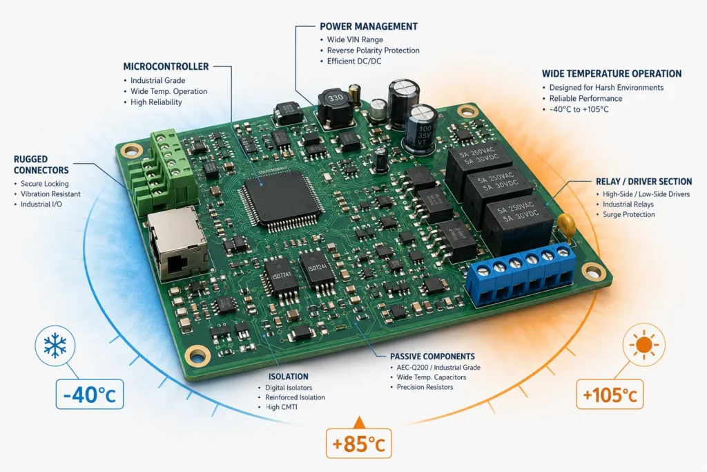
Then include self-heating, enclosure temperature rise, duty cycle, start-up, shutdown, and abnormal loads. A part can stay inside its ambient rating while its junction exceeds the recommended operating limit.
Use recommended operating limits rather than absolute maximum ratings. Absolute maximum values are survival boundaries, not continuous design targets. Apply documented derating to voltage, current, power, and temperature when the product requirements call for it.
Industrial PCB reliability also depends on temperature cycling, vibration, humidity, contamination, and mechanical support. Choose laminate, solder system, connectors, coatings, and mounting methods for the actual exposure. Coating is not automatically required, and it cannot correct poor spacing or trapped contamination.
A qualified component does not validate the assembled board. Solder joints, connectors, mounting points, and coatings create additional failure mechanisms. Test representative assemblies under temperature changes and mechanical loads that match the mission profile.
The IEC 60068-1 environmental testing framework supports tailoring test methods and severities to transport, storage, and operating conditions. The product owner should define the applicable tests, levels, duration, powered state, and acceptance criteria.
Passing one accelerated test does not prove a specific field life. IEC 61709 uses actual stresses and reference conditions to support component reliability predictions. The prediction still depends on suitable data and declared assumptions.
EMI and EMC Design for Industrial Environments
Industrial equipment may face fast switching, inductive loads, electrostatic discharge, surge events, and long external cables. EMC design must address both emissions from the product and immunity to outside disturbances.
Generic industrial standards include IEC 61000-6-2 for immunity and IEC 61000-6-4 for emissions. They apply only when their scopes fit and no relevant product standard takes precedence. The target market and product category determine the compliance plan.
For PLC or PAC products, review the scope of IEC 61131-2 before relying on a generic EMC standard.
Control noise at its source first. Keep high-current and switching loops small. Place decoupling close to the supplied device. Maintain continuous high-frequency return paths, and keep sensitive analog nodes away from noisy power sections.
Treat every external cable as part of the EMC path. Place filters and protection near the connector when the circuit requires them. Plan the chassis bond, shield termination, grounding approach, and enclosure together. A shield can fail when current must cross a long or high-impedance connection.
Texas Instruments’ EMC improvement guide illustrates how grounding, decoupling, loop control, filtering, and interface protection work together. Benlida’s guide to EMI shielding and EMC compliance explains the related terms and test context.
Define the exact test configuration before formal EMC work. Cable type, cable length, loads, firmware state, active ports, and enclosure bonds can change the result. Record them so failures and improvements can be reproduced.
Layout review and pre-compliance testing can expose risk early. Final EMC evidence must come from the complete product in its defined configuration. A bare PCB layout cannot guarantee system compliance.
Component Selection for Long Product Lifecycles
Do not assume every industrial product needs ten years of support. Define the planned production, service, repair, and spare-parts periods. Then build the BOM strategy around that timeline.
IEC 62402:2019 treats obsolescence as a lifecycle process. It covers planning, risk reduction during design, resolution strategies, and performance improvement. This is broader than checking stock once before release.
Review lifecycle status, product-change notices, end-of-life notices, package availability, and authorized sourcing for critical parts. Vendor longevity programs can help, but they apply only to listed products and stated periods. For example, NXP publishes part-specific longevity periods and important program conditions.
Approved alternates need more than the same footprint. Compare electrical limits, timing, tolerance, thermal behavior, package details, compliance, firmware effects, and availability. Recheck EMC, calibration, functional tests, and safety assumptions when the change can affect them.
Pin-compatible does not mean drop-in. A replacement may change power-up timing, leakage, analog response, thermal loss, or software behavior. Include those differences in the approval record.
A controlled alternative component sourcing process should document who may propose a substitute and who approves it. Keep the manufacturer part number, approved vendor list, revision, and no-substitution items clear.
Heavy Copper and Thermal Design for Industrial Power Circuits
Heavy copper can lower conductor resistance and spread heat across more area. It is not automatically required for an industrial automation PCB. Start with continuous or RMS current, transient current, fault behavior, voltage-drop limits, and allowable temperature rise.
Review the entire current path. Trace width, finished copper thickness, layer position, planes, vias, neck-downs, pads, thermal reliefs, terminals, and connectors can all set the limit. Parallel paths may not share current equally.
More copper can also change etching, spacing, lamination, drilling, solder mask, and cost. Use the lightest practical construction that meets the electrical and thermal requirements. The heavy copper PCB design guide explains these tradeoffs in more detail.
Thermal review should connect component loss to the board, enclosure, airflow, heat sink, interface material, and ambient conditions. Measure representative prototypes at defined loads. Heavy copper spreads heat, but it does not remove heat from a closed system.
Prototype measurements need a defined setup. Record ambient temperature, stabilization time, current waveform, sensor location, airflow, enclosure state, and measurement uncertainty. Otherwise, two temperature results may not be comparable.
Cost Optimization Without Weakening Reliability
Cost reduction is possible, but no change is automatically reliability-neutral. Compare total cost across materials, fabrication, components, assembly, testing, rework, inventory, and field service. A lower unit price can create a larger lifecycle cost.
- Remove unsupported over-specification. Confirm whether tighter tolerances, extra layers, heavier copper, or special finishes solve a documented requirement.
- Qualify alternates before a shortage. Approve electrical, thermal, mechanical, software, compliance, and sourcing differences through change control.
- Align the design with fabrication rules. Practical features and panel use can reduce process complexity without hiding electrical risk.
- Match testing to failure modes and volume. Keep required coverage while avoiding checks that duplicate the same evidence.
- Freeze revisions across all files. The BOM, Gerber or ODB++, centroid data, drawings, firmware, and test procedure must describe one build.
A credible cost-reduction case should record the original constraint, approved change, validation method, build scope, and measured result. Without that evidence, treat projected savings as an estimate. An industrial PCB engineering review should evaluate each proposed saving against the released requirements.
Industrial Control PCB Design Release Checklist
- Define operating, storage, transport, start-up, fault, and maintenance conditions.
- Record the applicable safety, EMC, environmental, and customer specifications with revisions.
- Set electrical, thermal, mechanical, creepage, clearance, and protection requirements for the actual system.
- Provide a revision-controlled BOM with exact part numbers, approved alternates, and substitution rules.
- Review the stack-up, copper, controlled impedance, power paths, return paths, connectors, and mounting.
- Define fabrication, assembly, inspection, programming, and functional test acceptance criteria.
- Release matching Gerber or ODB++, NC Drill, drawings, centroid data, firmware, and test files.
Industrial Control PCB Design FAQ
What operating temperature range is standard for industrial control PCBs?
No single range applies to every industrial control PCB. A -40°C to 85°C ambient rating is common for some industrial components, but supplier definitions vary. Define ambient, board, case, and junction limits for the actual enclosure and load. Then select and validate every critical part against those conditions.
How does component selection affect long-term industrial PCB reliability?
Component ratings, derating, parameter drift, package construction, thermal behavior, quality history, and traceability all affect risk. Lifecycle status also matters. An obsolete part can force an unplanned redesign. Document approved sources and alternates, then requalify changes that can affect product performance.
What EMI shielding methods are used in industrial control boards?
Methods can include shielded enclosures, board-level shield cans, cable shields, chassis bonds, filtered connectors, and guarded sensitive areas. The correct choice depends on the noise source, frequency, coupling path, and product construction. Good return paths, small loops, filtering, and protection often matter before added shielding.
Can PCB cost be reduced without affecting industrial reliability?
It may be possible, but the result cannot be assumed. Remove unnecessary specifications, improve manufacturability, qualify alternates, and match testing to defined risks. Verify each change against electrical, thermal, mechanical, EMC, safety, supply, and functional requirements before approval.
Prepare Your Industrial Control PCB for Review
Share the mission profile, schematics, stack-up, Gerber or ODB++, NC Drill files, fabrication drawings, BOM, centroid data, assembly drawings, firmware, and test requirements. Include the target standards, revisions, operating conditions, quantities, and approved substitution rules.
When the release package is ready,
and request a project-specific design and manufacturability review. Final materials, build rules, testing, pricing, and delivery conditions still require confirmation for the exact project.

