PCB DFM Checklist — What First-Time Buyers Need to Prepare
A PCB DFM checklist helps you prepare complete production files and identify manufacturing risks before fabrication starts. A design for manufacturability review may flag tight copper spacing, insufficient annular rings, missing drill data, or unclear stackup requirements. It helps reduce avoidable revisions and delays, but it does not guarantee a working product.
For a first-time buyer, the goal is simple: give the manufacturer clear requirements, resolve open questions, and approve the correct revision. You do not need to judge every technical detail yourself. You do need a design engineer who can approve changes that affect the circuit.
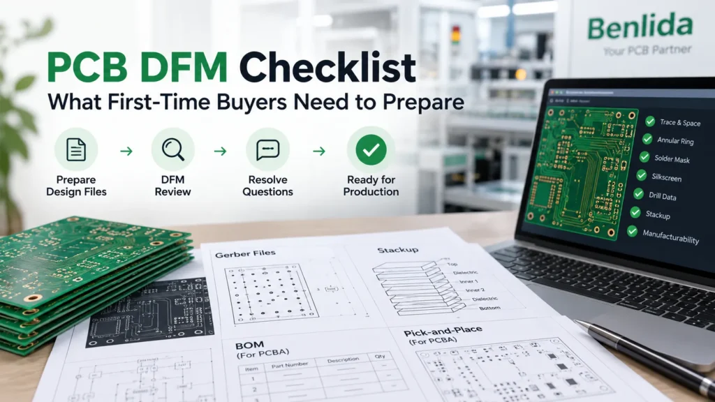
What Is PCB DFM Review?
PCB DFM review checks whether the submitted design can be fabricated using the manufacturer’s applicable processes. It compares the production data with the requested construction, tolerances, and manufacturing rules.
Run your CAD software’s design rule check, or DRC, before submitting files. As the KiCad design-rule documentation explains, checks depend on configured rules. A clean result is useful, but unsuitable rules can leave manufacturing risks unresolved.
A manufacturer’s review adds process-specific checks and questions about the exported files. It is not a substitute for circuit validation, reliability testing, or compliance assessment. If the order includes component assembly, agree on a separate assembly review scope as well. A bare PCB and an assembled PCBA need different checks.
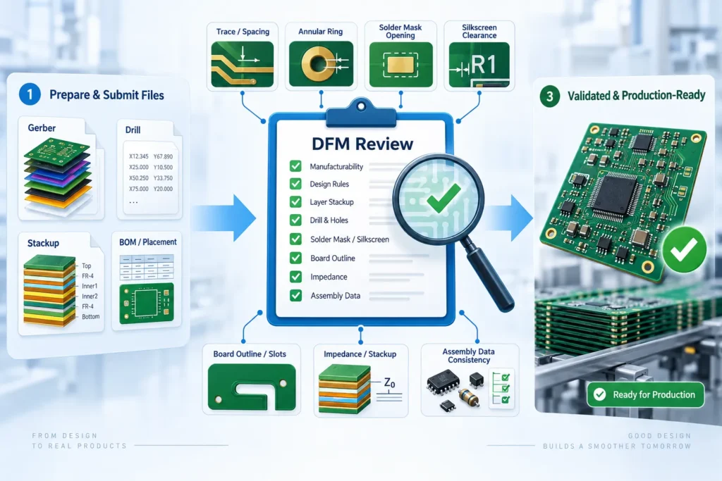
Files Required for DFM Review
Start with one clearly labeled package. Every file should belong to the same design revision. Identify any unfinished requirement instead of letting the manufacturer infer it.
For Bare PCB Fabrication
- Fabrication data: Gerber files for the required layers, or another format the manufacturer accepts, such as ODB++.
- Drill information: NC Drill data when supplied separately. Identify plated holes, non-plated holes, and slots.
- Fabrication drawing: Board outline, dimensions, cutouts, finished hole requirements, and critical mechanical tolerances.
- Construction and specifications: Layer order, material requirements, finished board thickness, copper requirements, surface finish, and any impedance or test requirements.
Layer images alone may not communicate the full build specification. The Gerber Job format provides a machine-readable way to carry manufacturing information such as materials and finish. A clear fabrication drawing and agreed specification can also communicate these requirements.
Use Benlida’s PCB fabrication file requirements to organize your submission. Include the quantity and whether you need individual boards or panels.
Additional Files for PCBA
For component assembly, add a BOM, pick-and-place or centroid data, and assembly drawings. Include fitted and not-fitted positions, polarity details, and any programming or functional test requirements. These files support assembly preparation; they do not replace fabrication data.
Check that reference designators match across the files. The PCB BOM preparation guide can help you organize component information before requesting an assembly review.
Common Design Errors Caught in DFM Review
DFM findings are not always circuit mistakes. Some are missing instructions or mismatches between the design and the selected process.
Trace width and copper spacing: Narrow traces or small gaps may fall outside the process limits for the chosen copper thickness. Check copper-to-edge clearance too. Do not copy a minimum value from another supplier without confirming its conditions.
Insufficient annular ring: The annular ring is the copper around a plated hole. Drilling and layer registration tolerances affect the remaining copper. Eurocircuits’ explanation of how annular rings are checked also distinguishes production drill diameter from finished hole diameter. Specify the finished hole size and tolerance. Ask the fabricator to confirm drill compensation and ring checks for its process.
Silkscreen and solder mask conflicts: Text may overlap exposed pads, or mask openings may not match the intended solderable areas. Ask what will be moved or removed. Important polarity marks must remain understandable.
Missing or inconsistent geometry: An unclear outline, omitted slot, or drill file from an older revision can create conflicting instructions. Review the exported package, not only the CAD layout.
Unclear impedance requirements: Give targets, tolerances, relevant layers, and applicable nets. The fabricator can assess the proposed stackup and trace geometry. That check does not replace signal-integrity analysis of reflections, crosstalk, and circuit behavior.
DFM Checklist for First-Time Buyers
Use this checklist before sending files and again before authorizing production. Mark each item as confirmed, not applicable, or open. Assign an owner to every open item.
- Define the order scope. State whether you need bare boards, assembly, or both. Include quantity, prototype or production use, and required delivery format. Identify the person who can approve technical changes.
- Freeze the submission revision. Put the project name and revision on the archive and drawings. Remove superseded outputs from the submission package. Keep a separate internal copy of earlier revisions for traceability.
- Confirm the accepted data format. Ask which fabrication files the supplier needs. Open your exports in a viewer. Check layer mapping, alignment, outline, drills, and slots rather than assuming the export succeeded.
- Run and review DRC. Use rules appropriate to the proposed construction. Resolve violations or document approved exceptions. Share any unresolved question with the manufacturer instead of sending an unexplained error report.
- Check holes and annular rings. Distinguish plated and non-plated features. Specify finished hole dimensions and tolerances. Ask engineering to confirm pad sizes and drill allowances, especially around connectors or tight mounting features.
- Review copper, mask, and markings. Check trace spacing, edge clearance, mask openings, and text near pads. Flag critical labels. Do not approve copper edits that may change electrical behavior without design-owner review.
- Confirm the build specification. Agree on layer order, material, board thickness, copper, and finish. Identify controlled-impedance features and constraints. Treat a proposed material or stackup substitution as a change requiring approval.
- Add assembly inputs when needed. Reconcile the BOM, placement data, and drawings. Mark not-fitted parts and orientation requirements. Ask about panelization and assembly access if these affect how the boards must be fabricated.
- Agree on inspection and testing. Define required bare-board checks and records. For PCBA, specify programming and functional test expectations separately. Confirm acceptance criteria; a DFM review is not a completed production test.
- Close questions before release. Record each issue, the agreed resolution, and the approver. Confirm the final file revision and any effect on price or schedule. Authorize production only against that agreed package.
What Happens After DFM Review?
The manufacturer may send engineering questions, marked-up images, or a list of proposed changes. A useful response identifies the affected location, the requirement that caused concern, and the decision needed.
Ask whether each item blocks fabrication or is only a recommendation. Send changes affecting connectivity, fit, impedance, or component placement to the responsible engineer. An accepted quotation should not be treated as blanket approval for design changes.
After a revision, regenerate all affected outputs and check the package again. Avoid emailing a new drill file while leaving outdated drawings in the production archive. Altium’s revision-controlled manufacturing release workflow illustrates how validation and related outputs can be tied to a specific release.
Keep the final archive, engineering responses, and approval record together. If a later change arrives, confirm whether the review and quotation must be reopened before work continues.
Why Free DFM Review Matters
When included in a quotation or order, a free DFM review can help a first-time buyer raise manufacturing questions early. Its value lies in clear, actionable feedback, not simply the absence of a review fee.
Confirm what is included. File screening, detailed engineering support, redesign, and simulation are not interchangeable services. Ask whether revised submissions receive another check. For a Benlida project, discuss the DFM review service and confirm its scope, timing, and any fees before work begins.
FAQ
What files are needed for a PCB DFM review?
For bare boards, provide accepted fabrication data, drill information, a fabrication drawing, and construction specifications. Include the revision and special requirements. For PCBA, also provide the BOM, placement data, assembly drawings, and relevant programming or test requirements. Confirm the supplier’s format requirements before submitting.
How long does a DFM review typically take?
There is no single turnaround time for every design. Timing depends on file completeness, board complexity, review scope, and clarification rounds. Ask for an estimate after the manufacturer receives the package. Confirm whether that estimate covers initial feedback or closure of all questions.
What is the most common DFM error found in first-time designs?
There is no universal ranking across suppliers and board types. Common findings include spacing violations, insufficient annular rings, silkscreen over pads, and missing or inconsistent files. First-time buyers should check both geometry and documentation rather than focusing on one presumed leading error.
Is DFM review free with a PCB order?
It depends on the supplier and order terms. Do not assume that an included review covers redesign, simulation, or unlimited revisions. For Benlida, ask whether your project qualifies for a no-charge review and request confirmation of the included checks before proceeding.
Prepare Your First PCB DFM Submission
Send one current-revision package with the board specifications, quantity, and a short list of open questions. Add assembly files only when the request includes PCBA. Clear inputs make the review easier to act on.
and ask Benlida to confirm the review scope, required files, timing, and any fees. Keep production on hold until the required technical questions and approvals are complete.

