

FPC Assembly Guide — SMT, Stiffener & Connector Options
What Is FPC Assembly?
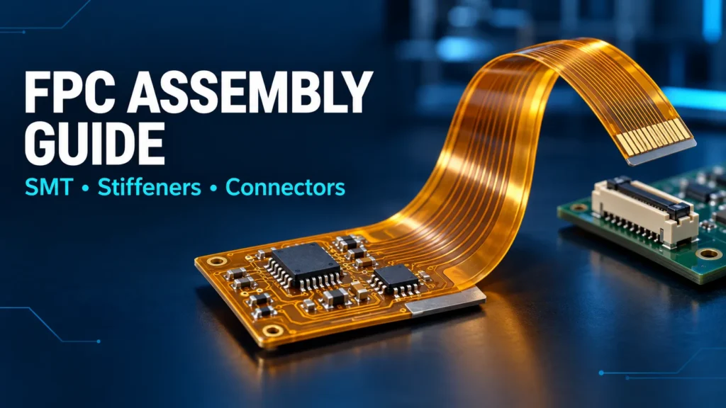
FPC assembly adds components and electrical connections to a flexible printed circuit. It may include surface-mount soldering, local reinforcement, and connector installation. Some flex tails plug into ZIF sockets; others use soldered connector pairs or direct solder joints. The process needs controlled support and a thermal profile validated for the complete assembly.
A bare FPC is the unpopulated circuit. Once components are fitted, it becomes a flexible circuit assembly. A bonded stiffener provides mechanical support; it does not, by itself, turn the circuit into a rigid-flex PCB.
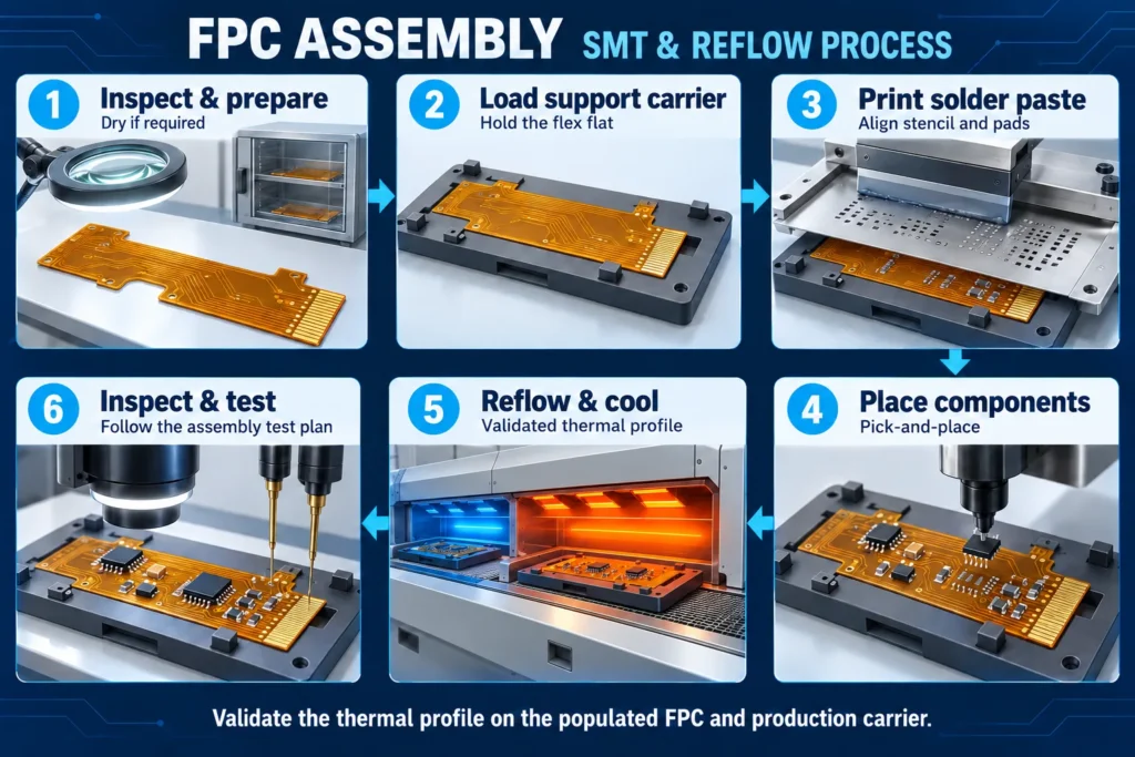
This FPC assembly guide follows the decisions that matter before production. A typical SMT route includes incoming inspection, moisture preparation when required, fixture loading, paste printing, component placement, reflow, and inspection. Connector mating and final forming follow the approved process. Stiffener bonding must be placed at the appropriate stage, not automatically added to the soldering step.
SMT on Flexible Circuits — Reflow Profile Adjustments
SMT on a flex circuit uses the familiar print-place-reflow sequence. The difference is how the thin circuit stays flat and how its materials respond to heat. Copper coverage, components, reinforcement, and the carrier all affect the heating pattern.
Start with the solder paste’s recommended process window. Check it against component limits and the approved laminate, coverlay, adhesive, and stiffener construction. Polyimide film’s heat resistance alone does not qualify the finished assembly. Flex does not always require a lower peak temperature, and reducing heat without measurement can leave poor joints.
Measure a representative populated assembly on its intended production carrier. Indium’s thermocouple guidance explains why bare-board temperatures do not reliably represent a populated board. Check critical joints, high-mass areas, and heat-sensitive locations. Record the heating rate, peak, time above the solder alloy’s liquidus, and cooling behavior.
Moisture control is a separate preparation step. FCT’s handling and assembly guidance stresses drying flex materials before elevated-temperature processing. Obtain the drying method from the fabricator for the actual construction. Include surface-finish and fitted-component limits when planning repeat processing. Do not copy a generic bake temperature or duration.
After drying, control storage and exposure before soldering. Revalidate the profile when a material, component, carrier, or loading condition changes enough to affect heating. A saved oven recipe is useful only when the measured assembly remains within its approved limits.
Stiffener Bonding During Assembly
A permanent stiffener supports a connector, component area, or mounting point. A temporary carrier supports the circuit while machines print, place, and solder. One may be needed even when the other is present.
For FPC stiffener bonding, specify the material, adhesive grade, location, finished thickness, and acceptance criteria. The bond may be completed during circuit fabrication or in a separate assembly operation. Decide the sequence before designing fixtures.
Heat-bonded systems require their own process controls. For example, Pyralux LF Sheet Adhesive is a B-staged acrylic adhesive used for stiffener bonding. Its data sheet provides typical lamination ranges. A solder-reflow pass does not automatically provide the pressure, time, and bondline temperature needed to finish that operation.
Pressure-sensitive adhesives depend on suitable surfaces and application pressure. Some grades tolerate specified reflow conditions. The 3M 9077 technical data sheet describes an FPC attachment tape with a heat-resistant liner for lead-free reflow environments. This does not qualify other tapes or every assembly cycle.
If bonding occurs after SMT, the tooling must avoid loading components or fragile joints. If it occurs before SMT, qualify the bond through subsequent heating. Inspect registration, edge lift, adhesive encroachment, and connector-tail thickness. Use the FPC stiffener design guide for the underlying material and placement decisions.
Connector Attachment Methods (ZIF, Board-to-Board, Soldered)
FPC connector assembly starts with the exact mating interface. Decide whether the connection must be removable, how it will be reached, and where mating forces will go. Pitch alone does not establish compatibility.
ZIF Connectors
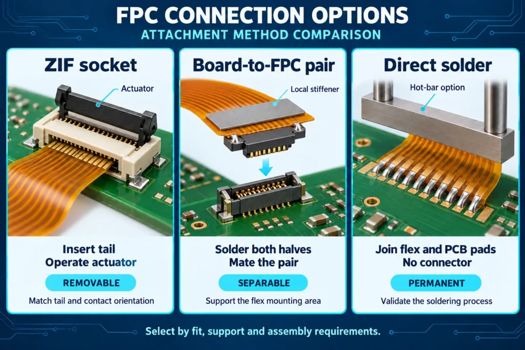
A common ZIF arrangement uses a socket soldered to a rigid PCB. The prepared flex tail enters the socket and is retained by its actuator. The tail is not soldered to the socket contacts.
Match contact orientation, tail geometry, and finished mating-area thickness to the connector drawing. Include reinforcement and adhesive where present. Hirose’s FH29 catalog illustrates why insertion angle, alignment features, and actuator handling are part-specific. Follow the selected part’s procedure; do not assume every ZIF uses straight, parallel insertion. For FH29, complete soldering before inserting the FPC; do not reflow with the tail connected.
Board-to-Board and Board-to-FPC Connectors
These interfaces use a matched connector pair soldered to the mating circuits. The flex-side mounting region needs appropriate reinforcement and support. Review the pad pattern, clearance, mating direction, and removal method.
Hirose’s BM20 guidance addresses flex reinforcement and mating loads. It also warns that overconstraining the flex can transmit impact to the connector. Plan support around the actual housing and service conditions. Do not use the flexible tail as a pull handle.
Direct Solder Connections
A direct solder joint connects flex pads to another circuit without a detachable connector. Hot-bar soldering is one possible process. As AMADA WELD TECH explains, a heated tool applies controlled heat and force to prepared pads, then holds them through solder solidification. Alignment, solder quantity, and heat flow need validation.
The table summarizes candidate uses. “Best Use” is a starting point, not a universal ranking.
FPC Connector Type Comparison
| Connector Type | Attachment Method | Best Use |
|---|---|---|
| ZIF FPC connector | Insert the prepared flex tail into a board-mounted socket; operate its actuator as specified. | Removable flex-to-board links with access to the actuator. |
| Board-to-board / board-to-FPC connector | Solder a matched connector pair to the circuits; support the flex mounting area. | Compact modules needing a separable connection and controlled mating support. |
| Direct solder connection — no connector | Join flex and PCB pads by a qualified soldering process, such as hot-bar soldering. | Permanent connections where routine disconnection is unnecessary. |
Handling and Fixture Requirements for Flex Assembly
The flex circuit assembly process depends on repeatable positioning. An unsupported panel may move during printing or placement. A carrier or pallet holds the intended working area flat. Minco’s flex design guide describes assembly pallets that support component placement and soldering.
Review tooling with the assembler before releasing the panel layout:
- Provide agreed locating features and visible fiducials for alignment.
- Support printing and placement zones without blocking pads or component clearance.
- Check that the hold-down method tolerates processing and releases without damaging the circuit.
- Account for the carrier during thermal profiling and provide access for inspection.
- Define how parts leave the panel or fixture without bending populated regions.
Use ESD controls appropriate to the fitted components. Keep exposed contacts and bonding surfaces clean. Transport assemblies in supports that prevent loose tails from snagging. Plan final forming around the approved bend zones rather than bending the circuit wherever handling is convenient.
Show the installed shape and any repeated movement in the mechanical drawing. The FPC bend radius design guide covers that design decision. Do not treat flexibility as permission to crease a circuit or bend through its solder joints.
Common FPC Assembly Defects and Prevention
Start with the observed defect, then investigate the responsible process. Similar-looking failures can have different causes. These checks are diagnostic starting points, not a ranked list of failure rates.
Shifted components or solder bridges. Check fixture stability, print alignment, paste deposits, and placement before changing oven settings. Compare inspection results before and after reflow to identify when the problem appears.
Tombstoned passive components. A small component can stand on one end when its pads wet unevenly. Indium distinguishes tombstoning from BGA head-in-pillow defects, which involve a different failure to form a sound joint. Review pad balance, paste transfer, and thermal behavior rather than blaming every open connection on flex movement.
Blistering or layer separation. Review moisture exposure, drying records, material compatibility, and measured heating. Quarantine affected parts for assessment. Simply running them through reflow again does not establish that the damage is repaired.
Lifted stiffeners or poor connector contact. Check bonding surfaces, adhesive processing, alignment, and the finished tail dimensions. For intermittent connections, also inspect insertion depth, actuator condition, contact orientation, and mechanical loading.
Agree on inspections and electrical tests before the build. Define which joints are accessible and which need additional inspection. A bare-board continuity result does not verify component placement, solder integrity, or assembled functionality.
FAQ
Does FPC assembly require a different reflow profile than rigid PCB?
It requires a profile validated for the actual flex assembly. The settings may differ because of its construction, components, and carrier. Do not assume the peak must always be lower. Confirm that measured joint temperatures meet the soldering window without exceeding material or component limits.
What connector types work best with flexible circuits?
ZIF sockets suit removable flex tails when the actuator is accessible. Board-to-FPC connector pairs suit supported mating areas. Direct solder joints suit permanent connections. Select by mechanical fit, electrical requirements, service access, and the manufacturer’s application instructions, not connector name alone.
Can stiffeners be bonded during the same assembly pass as SMT?
Not automatically. An already bonded stiffener may travel through SMT if its bond is qualified for that cycle. Creating the bond during the same heating step is a separate process-development question. Adhesive pressure, curing requirements, and access may require an earlier or later operation.
What causes the most common FPC assembly defects?
Recurring causes include poor support, printing or placement errors, uneven heating, moisture, and incorrect connector or stiffener assembly. The dominant cause varies by design and process. Use inspection evidence and traceable build records to isolate it before changing materials or settings.
Need Turnkey FPC Assembly?
Discuss your project through Benlida’s FPC manufacturing and assembly services page, and confirm the required assembly scope. For a turnkey request, identify who supplies the circuit and components, which bonding and connector operations are needed, and how the assembly will be tested.
Request an FPC assembly quote with Gerber or ODB++ data, drill files, the BOM, and pick-and-place data. Include fabrication and assembly drawings, stiffener and adhesive details, connector part numbers, quantity, and revision. Add the installed shape, movement requirements, and any testing or firmware instructions.
Confirm the proposed materials, process sequence, inspection coverage, and delivery scope before releasing production.