

FPC Bend Radius Design Guide: Rules, Calculations & Best Practices
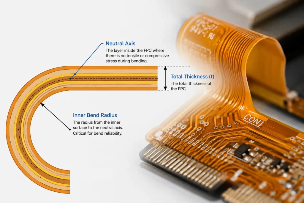
Flexible printed circuits (FPCs) are thin, bendable boards. You’ll find them in foldable phones, smartwatches, automotive sensors and medical devices.
They fit into tiny spaces and make products sleeker. But there’s one critical rule you can’t skip: the FPC bend radius.This guide breaks down basic rules, easy calculation methods and practical design tips. You’ll learn to build flexible circuits that last — and if you need a manufacturer who can review your design before production, Benlida’s FPC engineering team offers free DFM review with every order.
The bend radius is the size of the inner curve when you bend an FPC. It measures how tight the bend is.
Get this number wrong, and your FPC can crack, peel or stop working. It directly decides how long your product lasts. For production-stage checks, see the FPC process control guide.
This guide from Benlida’s engineering team breaks down basic rules, easy calculation methods and practical design tips.You’ll learn to build flexible circuits that last.
Minimum Bend Radius Rules for FPC
The electronics industry follows the IPC-2223 standard for bend radius limits. The rules depend on two things: how you use the FPC and how many layers it has.For minimum bend radius guidance, designers commonly refer to IPC-2223, as summarized in Sierra Circuits’ flex PCB design guidelines
First, two key terms:
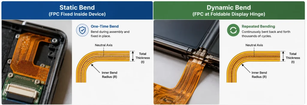
Static bending: You bend the FPC once during assembly. It stays bent forever, with no repeated movement.
Dynamic bending: The FPC bends again and again during use — for example, in a phone hinge or watch band.
We use the “R/t ratio” to set rules. R is the bend radius. t is the total thickness of the FPC (all layers included).
| FPC Type | Static (One-Time Bend) | Static (Long-Term Fixed) | Dynamic (10,000+ Bends) | High-Cycle Dynamic (100,000+ Bends) |
|---|---|---|---|---|
| Single-layer FPC | 3 × total thickness | 10 × total thickness | 10–25 × total thickness | 50 × total thickness or more |
| Double-layer FPC | 6 × total thickness | 10 × total thickness | 15–35 × total thickness | 100 × total thickness or more |
| Multilayer FPC (3+ layers) | 10 × total thickness | 20 × total thickness | 50 × total thickness (not recommended) | Not advised |
These are the bare minimum values. For medical, automotive or other high-reliability products, add a 1.5× safety margin.
Simple example: A 0.1 mm single-layer FPC for a watch hinge needs at least a 1.0 mm bend radius to survive 10,000 bends.
How to Calculate FPC Bend Radius
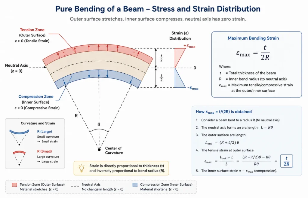
ou don’t need complex math for most designs. Here are two straightforward ways to calculate.
1. Quick Estimation (R/t Method)
This is the most common method for early design work.
Formula: Minimum bend radius = K × total thickness
K = a number from the table above, matched to your use case
Total thickness = all layers of the FPC added together
Use this for quick feasibility checks and initial design reviews.
2. Strain-Based Precise Calculation
For high-reliability products, calculate the actual stress on the copper wires inside the FPC.
Formula: Maximum strain = total thickness / (2 × bend radius)
Copper is the weakest part of an FPC. Safe strain limits:
ED copper (low-cost standard type): 0.3–0.5% — only for static use
RA copper (flexible and durable): 0.5–1.0% — required for dynamic use
Rearrange the formula to find the smallest safe bend radius for your design.
3. How Bend Radius Affects Lifespan
For products that bend repeatedly, small changes make a huge difference.
If you cut the bend radius in half, the FPC will only last 1/8 as long.
Adding just 1 mm to the radius can make it last 3–5 times longer.
Design Tips to Avoid FPC Failure
Follow these simple rules to make your FPC much more reliable.
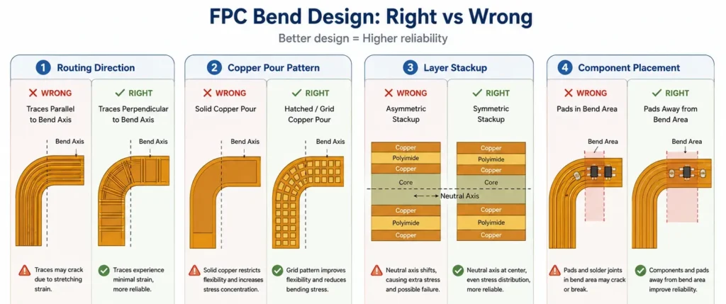
Run wires perpendicular to the bend line
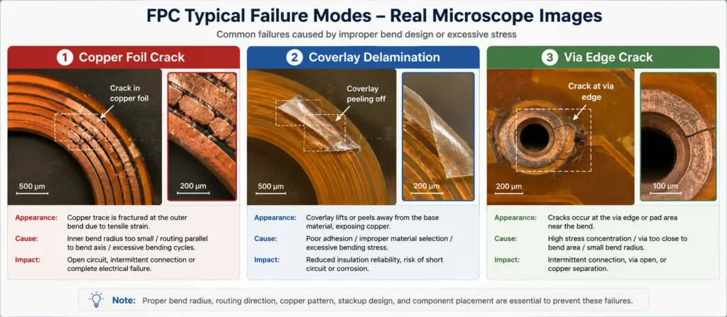
Wires that run parallel to the bend are 4–5 times more likely to crack. Always cross the bend at 90 degrees.
Make the bend area as thin as possible
Thicker boards need bigger bend radii. Remove extra layers and copper from the bend zone if you can.
Use symmetrical layer stacks
Unbalanced layers shift all the stress to one side. Mirror copper and base layers evenly to spread stress out.
Keep components and vias away from the bend area
Vias, pads and stiffeners create stress hotspots. Keep them at least 1.5–2 mm away from the bend line.
Use RA copper for dynamic designs
RA copper resists cracking much better than cheaper ED copper. It’s a must for any product that bends repeatedly.
Use grid copper instead of solid copper in bend zones
Solid copper makes the board stiff. Use a mesh pattern for ground layers to keep flexibility.
Add a Bend Radius Indicator to Your Fabrication Drawing
Include the minimum bend radius value directly on your Gerber or fabrication drawing. This ensures the manufacturer can verify your design meets the minimum radius before production starts. At Benlida, our engineering team checks this during DFM review—catching bend radius violations before a single board is made. For integrated rigid and flexible sections, also review the rigid-flex PCB design guide.
Common FPC Bend Radius Mistakes
Even experienced designers make these mistakes. Avoid them to save time and cost.
Using one-time bend rules for permanent bends
The 3:1 ratio (bend radius to thickness ratio) is only for assembly. A permanent bend needs at least 10:1 to last for years.
Running wires parallel to the bend axis
This is the #1 layout mistake. Always double-check wire direction before finalizing your design.
Ignoring stress at bend edges
Most cracks start at stiffener edges or pad edges — not in the middle of the bend. Leave clear space on both sides.
Using ED copper in dynamic products
ED copper is cheaper, but it wears out fast with repeated bending. It can cut lifespan by 70–80%.
Only counting copper thickness
Always use the total stack thickness for calculations. Include base film, glue and protective cover layer.
Need an FPC Manufacturer for Your Next Project?
Benlida manufactures flexible PCBs with fast prototype lead times — 2-layer FPC prototypes in as little as 24 hours. Our engineering team reviews every design before production to catch bend radius issues early.
Learn more about our
FAQ
What is the minimum bend radius for single-layer FPC?
For a one-time assembly bend: 3 times the total thickness.
For a permanent fixed bend: at least 10 times the thickness.
For repeated bending (10,000+ cycles): 10–25 times the thickness.
For high-cycle hinges (100,000+ cycles): 50 times the thickness or more.
How does bend radius affect FPC reliability?
A tighter bend puts more stress on the copper and material.
A larger bend reduces stress, making the FPC less likely to crack or peel.
For dynamic use, lifespan changes roughly with the cube of the radius. Small increases in radius give big lifespan gains.
What happens if FPC bend radius is too tight?
Severe cases: Copper cracks right away, and the circuit stops working after assembly.
Milder cases: Tiny hidden cracks form. They grow over time and cause on-and-off failures later in the field.
How many times can FPC be bent before failure?
It depends on the design.
A well-made single-layer FPC with thin RA copper can last 100,000+ bends.
A double-layer FPC at minimum dynamic specs may last 10,000–30,000 bends.
At the tightest static bend limit, it might break after fewer than 100 bends.
What is the difference between static and dynamic FPC bending?
Static bending: Bend once, stay bent forever. Like an FPC shaped to fit inside a device case.
Dynamic bending: Bend over and over during normal use. Like a cable in a folding phone hinge.
Dynamic bending needs much larger radii and higher-quality materials.