

FPC Stiffener Design Guide — Types, Placement & Thickness Rules
What Is an FPC Stiffener?
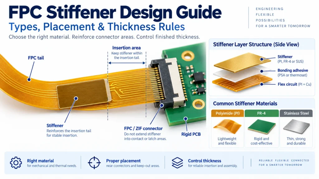
An FPC stiffener is a rigid or semi-rigid material bonded to a flexible printed circuit for local mechanical support. It reinforces connector tails, mounting points, or component areas. Common choices include polyimide, FR-4, and stainless steel. Selection depends on the required support, available height, and where the circuit must bend.
A stiffener supports a selected area; it does not make the whole circuit rigid. It also does not add an electrically interconnected rigid layer. A flex circuit with bonded reinforcement is therefore not automatically a rigid-flex PCB.
Good FPC stiffener design starts with three questions: What must this area support? What finished thickness does the interface require? Where should bending occur? For a broader technology decision, see the FPC vs rigid PCB comparison.
Common Stiffener Materials — Polyimide, FR-4, Stainless Steel
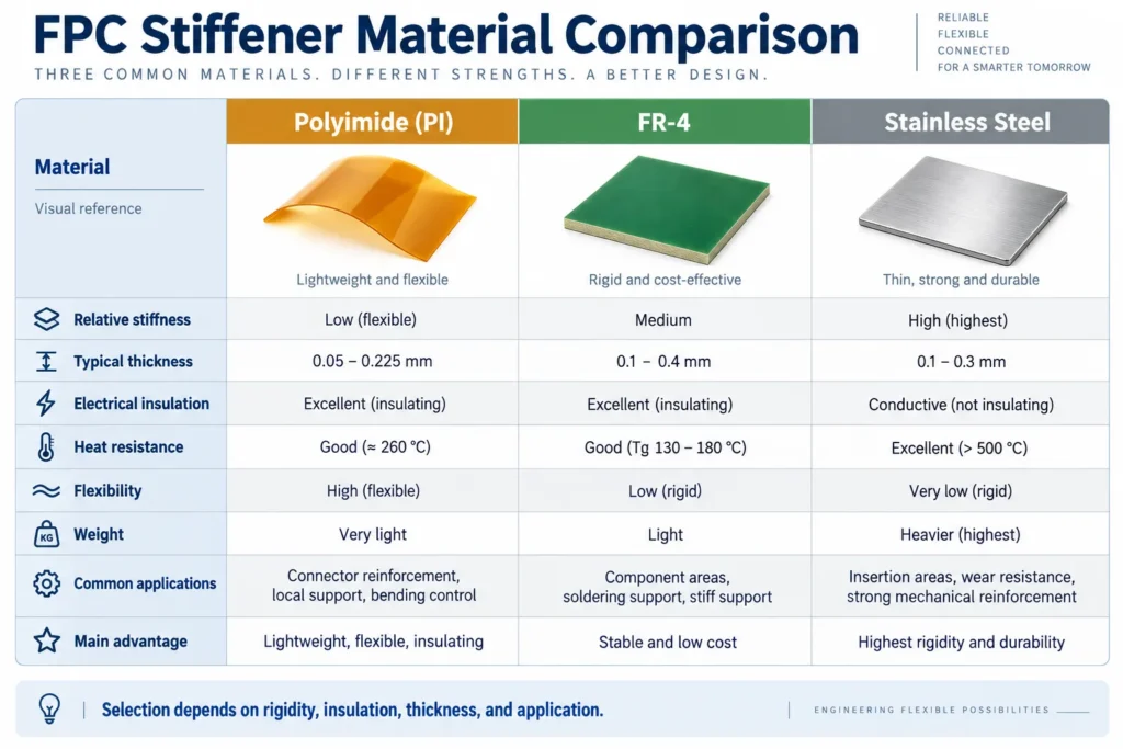
Different FPC stiffener types solve different mechanical problems. Compare the complete bonded structure, not just the material name. Thickness, outline, adhesive, and mounting conditions all affect how much support it provides.
Polyimide
Polyimide, or PI, adds thickness and handling support while remaining relatively compliant. It is useful for connector tails that need a controlled insertion thickness. However, a thin PI film is not a substitute for a rigid support plate under a heavily loaded connector.
FR-4
FR-4 is a glass-reinforced epoxy material. It provides a rigid base for component areas, connector bodies, and selected mounting features. Check its added height against the enclosure. Specify the material grade and mechanical requirements rather than treating every FR-4 sheet as identical.
Stainless Steel
Stainless steel can provide strong local support where space is limited. Unlike PI and bare FR-4, it is electrically conductive. Define insulation, conductor clearance, and edge finish. Do not assume a metal stiffener is grounded or that its bonding adhesive alone provides sufficient insulation.
The PI examples below come from Minco’s flex design guide. The FR-4 examples appear in the All Flex design guide. These are published vendor examples, not universal ranges or Benlida manufacturing limits. Adhesive thickness is additional.
Stiffener Material Comparison
| Material | Rigidity | Thickness Range | Best Use |
|---|---|---|---|
| Polyimide | Relatively compliant; adds local support | Published examples: 0.025, 0.050, 0.075, and 0.125 mm | Connector-tail thickness adjustment and handling support |
| FR-4 | Rigid support; thickness strongly affects behavior | Published examples span 0.25–1.57 mm in discrete options | Component areas, connector support, and mounting features |
| Stainless steel | High rigidity at comparable geometry | Connector- and load-specific; confirm available options | Compact reinforced areas with defined electrical isolation |
Use the table to compare starting points, not to select a finished stack-up without checking the application.
Stiffener Placement Rules Near Connectors and Mounting Holes
Start With the Exact Connector Drawing
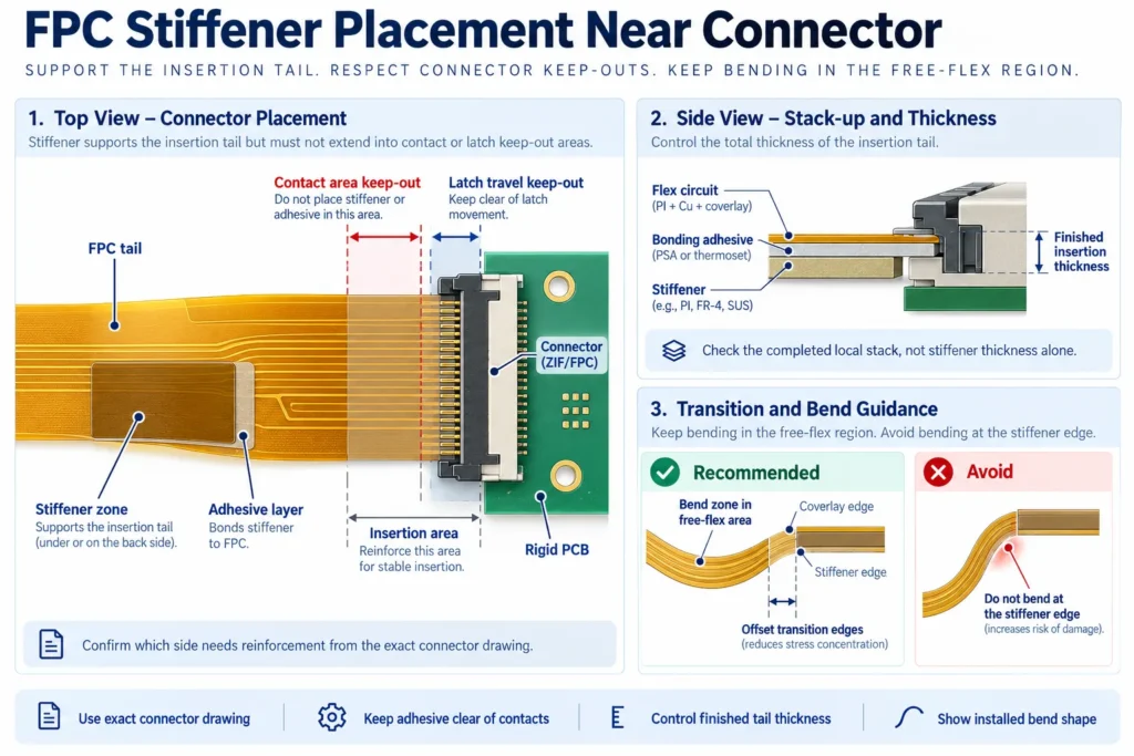
An FPC connector stiffener must match the connector’s mechanical requirements. For an inserted tail, check contact orientation, insertion length, width, and finished thickness. Confirm which side needs reinforcement. Do not copy the stiffener side from another design with a different connector.
A soldered board-to-FPC connector has different support needs from a ZIF connector tail. Review mating force, board support, and the manufacturer’s reinforcement instructions separately. Keep the stiffener and adhesive clear of contacts, latch travel, and other defined keep-out areas.
Plan the Transition Into the Flexible Area
A stiffener creates a change in bending stiffness. Repeated bending directly against a hard edge can concentrate strain. Keep the intended bend in the flexible region and review the transition with the fabricator.
All Flex’s guide recommends separating the stiffener and coverlay termination edges. This avoids placing both changes at one line. Agree the required overlap or offset for your construction. Do not treat one supplier’s example distance as a universal rule.
Show the installed shape and any service movement in the drawing. This makes flex circuit stiffener placement easier to assess than a flat outline alone.
Support Mounting Loads
At mounting holes, review the complete fastening arrangement: stiffener, hole clearance, washer or support surface, and clamping load. Avoid relying on unsupported flex to carry the fastener load. Dimension the holes and stiffener outline from common drawing references, and allow for alignment tolerances.
Thickness Selection and Its Effect on Flexibility
Select polyimide stiffener thickness from the required finished connector-tail thickness, not the other way around. The inserted stack includes the local circuit construction, bonding layer, and stiffener. Surface finish and other layers count where they are physically present.
For example, Hirose’s FH40 catalog specifies a 0.30 ± 0.05 mm mated FPC/FFC thickness. That is the completed tail thickness, not a 0.30 mm stiffener requirement. Other connector series may require a different construction.
Build a local cross-section at the actual insertion area. Coverlay openings can make that area thinner than the covered circuit nearby. Include finished adhesive thickness and manufacturing tolerances. A nominal sum that fits the connector is not enough if the maximum stack exceeds its limit.
On the drawing, specify both the individual reinforcement and the required finished thickness at the inspection location. Agree how the fabricator will measure it.
Adding reinforcement reduces bending in the supported region. It can also move bending toward the edge. It does not create one new bend-radius rule for the entire FPC. Review the free-flex stack and the stiffener transition separately.
Use the FPC bend radius design guide for related design considerations. Distinguish one-time installation bends from repeated motion. Validate the intended radius, movement, and life on representative assemblies.
Adhesive Types for Stiffener Bonding
Thermoset adhesives and pressure-sensitive adhesives, or PSAs, can both bond stiffeners. Choose the exact grade around the substrates, assembly sequence, service temperature, and mechanical loads. The stiffener material alone does not determine the adhesive family.
Thermoset Adhesives
Thermoset systems use a controlled curing process. For example, Pyralux LF Sheet Adhesive is a B-staged modified acrylic adhesive with stiffener bonding among its stated uses. B-staged means partially cured before final processing.
Use the selected adhesive supplier’s processing requirements. Confirm compatibility with the circuit and reinforcement. Do not transfer a cure temperature, pressure, or duration from an unrelated material.
Pressure-Sensitive Adhesives
PSAs depend on suitable surface contact and application conditions. Some grades address high-temperature FPC attachment, including solder-reflow environments, as shown in the 3M 9077 technical data sheet. Others may not suit those conditions.
Check the complete thermal profile, exposure time, and repeated cycles. A peak-temperature claim alone does not qualify the bonded assembly. Agree surface preparation and application pressure. Then assess representative parts for edge lifting, bond movement, or separation after relevant thermal and mechanical tests.
Common Stiffener Design Mistakes
Before releasing the design, check for these avoidable specification gaps:
- Specifying only stiffener thickness. Also define the finished connector-tail thickness, tolerance, and measurement location.
- Missing the connector part number. Similar-looking connectors can require different tail constructions or reinforcement layouts.
- Putting a bend at the stiffener edge. Show the bend zone and installed shape, including movement during servicing.
- Leaving adhesive unspecified. Record its grade, finished thickness, coverage, and relevant processing requirements.
- Ignoring metal edges. Define insulation, electrical clearance, and acceptable edge condition before approving stainless steel.
- Using an incomplete drawing. Mark each zone’s side, outline, material, thickness, hole pattern, and position tolerance.
For multiple zones, label them clearly and provide a local stack-up for each different construction. Ask the fabricator to flag conflicts before production. Any agreed material or layout change should appear in the released revision.
FAQ
What is the most common FPC stiffener material?
Polyimide is a common choice for connector tails. FR-4 is often used for more rigid component or mounting support. There is no single best material for every FPC. Select it by the interface, mechanical load, and available space.
How thick should an FPC stiffener be?
There is no universal thickness. For connector tails, work backward from the connector’s finished-thickness requirement, including adhesive and circuit layers. For other zones, evaluate support, enclosure clearance, and the bonded structure.
Does adding a stiffener affect the bend radius nearby?
It can change where bending occurs and concentrate strain near the transition. Keep the intended bend out of the reinforced area. Check the transition and free-flex radius for the actual stack-up and motion.
Can Benlida manufacture FPC with multiple stiffener zones?
Send Benlida a drawing showing each zone, material, thickness, adhesive, and bend area for a project-specific feasibility check. Confirm the available constructions and manufacturing scope before treating a multi-zone design as approved.
Designing an FPC with Stiffener Zones?
Prepare Gerber or ODB++ data, drill files, and a fabrication drawing. Include the flex stack-up, stiffener details, connector part number, finished-tail tolerance, installed shape, quantity, and revision. Add assembly drawings and thermal-process requirements where components will be fitted.
Discuss these details through Benlida’s FPC manufacturing services. Ask the team to confirm material availability, bonding options, and the scope of the DFM review. Project review can identify manufacturing concerns; it does not replace mechanical or reliability validation.