

Ceramic PCB Reliability Testing Methods
Why Reliability Testing Matters for Ceramic PCBs
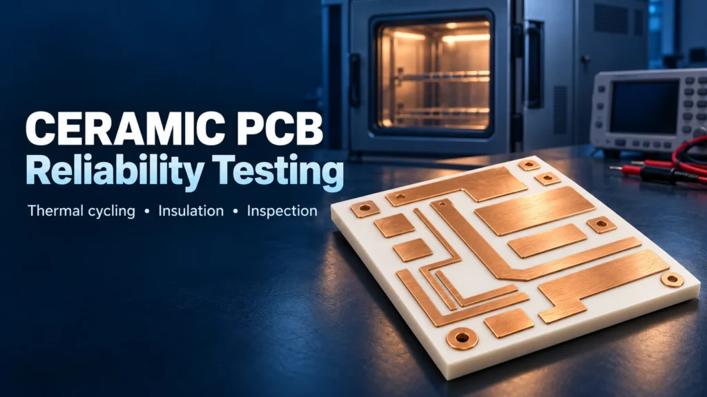
Ceramic PCB reliability is evaluated through thermal cycling, thermal shock, electrical insulation tests, and physical inspection. These methods provide evidence under defined conditions. They do not guarantee that every board will remain free of cracks or interface damage throughout its service life.
Aluminum nitride (AlN) and alumina (Al2O3) both support demanding electronic applications. However, reliability depends on more than the ceramic name. The metal pattern, bonding process, thicknesses, mounting, and operating environment also matter.
First, identify what was tested: an unmetalized ceramic sample, a patterned bare board, or an assembled module. These are different test objects. A material data sheet cannot replace a finished-board report. A bare-board report cannot establish the reliability of solder joints or attached components.
For background on the material families, see our ceramic PCB vs FR-4 comparison. The focus here is how to evaluate test evidence for a specific construction.
The table summarizes complementary checks. “What It Validates” applies only within the agreed test conditions, sample scope, and detection limits.
Ceramic PCB Reliability Test
| Test | Method | What It Validates |
|---|---|---|
| Thermal cycling | Repeat a defined temperature profile with specified transitions and dwell periods. | Resistance to repeated thermal strain within that profile, assessed by agreed checks. |
| Thermal shock | Apply rapid temperature changes using a specified medium and transfer method. | Resistance to abrupt temperature changes under the selected conditions. |
| Dielectric withstand | Apply a specified voltage across an insulation path for a defined duration. | Ability to meet the stated withstand and current limits during the test. |
| Insulation resistance | Measure resistance under specified DC voltage, timing, and environmental conditions. | Resistance between the tested conductors under those conditions. |
| Physical inspection | Compare baseline and post-test images; add suitable internal-interface inspection when needed. | Whether detectable cracks, separation, or other specified physical changes occurred. |
Thermal Cycling Test — Method and Pass Criteria
A ceramic PCB thermal cycling test repeatedly exposes specimens to low and high temperatures. Here, thermal cycling means a defined ramp-and-dwell profile. Thermal shock emphasizes rapid transitions. Test names vary, so compare the actual profiles.

IEC 60068-2-14:2023 provides a framework for studying the effects of temperature changes on specimens. A reference to the standard alone is not a complete test specification. The selected procedure and severity still need to match the project.
Copper and ceramic expand by different amounts as temperature changes. Their coefficient of thermal expansion, or CTE, describes this behavior. Rogers’ discussion of metallized ceramic reliability explains how this mismatch creates stress, including near copper edges.
Define the following before testing:
- Material grade, ceramic and metal thicknesses, pattern, and sample quantity.
- Temperature endpoints, change rate, dwell conditions, and cycle count.
- Specimen mounting, temperature measurement, and inspection intervals.
- Baseline measurements and the allowed changes after exposure.
Pass criteria might include specified crack limits, interface integrity, and electrical results remaining within agreed limits. They must be established before the test. There is no single cycle count that qualifies every ceramic board.
Surface inspection alone may miss internal separation. CALCE’s scanning acoustic microscopy guidance describes inspecting delamination in direct-bonded copper substrates. Select an inspection method suited to the structure and defect of interest.
Thermal Shock Testing for High-Power Applications
Thermal shock testing stresses a specimen through rapid temperature changes. Different parts of the structure may change temperature at different rates. This can stress the ceramic and its bonded interfaces.
The important measurement is the specimen’s temperature response, not just the chamber setting. ESPEC’s explanation of thermal shock shows why sample mass, airflow, and heat transfer affect the result.
Record whether the method uses air or liquid, the transfer conditions, and the time allowed for stabilization. Identical temperature endpoints and cycle counts do not make two different methods equivalent.
For a high-power design, choose the exposure to address a defined concern. A rapid-change test may help investigate cracking or interface separation. It does not reproduce every condition inside an operating power module.
Review the assembled module separately when components, attachment layers, or cooling hardware affect the load. Bare-board results should not be extended to those added structures without supporting evidence.
Dielectric Withstand and Insulation Resistance Testing
Ceramic PCB dielectric testing checks electrical insulation under stated conditions. Dielectric withstand testing, often called hipot testing, applies a specified AC or DC voltage between designated conductive regions. The specimen must meet the procedure’s requirements for breakdown and measured current during the test.
Insulation resistance testing measures resistance under specified DC conditions. Chroma’s comparison of withstand and insulation resistance tests explains their different outputs. They answer related questions but are not interchangeable.
Identify the insulation path clearly. A test between top and bottom metallization differs from a test between adjacent surface conductors. Electrode geometry, surface condition, temperature, and humidity can affect interpretation.
Also record voltage type, ramp, duration, and measurement timing. AC measurements include a capacitive current component. DC measurements initially include charging current. A reported current value needs its measurement conditions.
A material’s dielectric strength is not automatically a finished board’s working-voltage rating. IEC 60243-1 addresses short-time electric strength of solid insulation at power frequencies. That scope differs from establishing long-term performance in a complete product.
Test medium matters too. For example, DOWA’s metal-ceramic substrate specifications explicitly identify dielectric strength measured in insulating oil. Such a value should not be transferred directly to an air-exposed board layout.
Agree on electrical checks before and after thermal exposure when insulation degradation is a concern. A passing result only covers the tested paths and conditions. It does not independently prove the absence of cracks or delamination.
AlN vs Al2O3 Reliability Differences
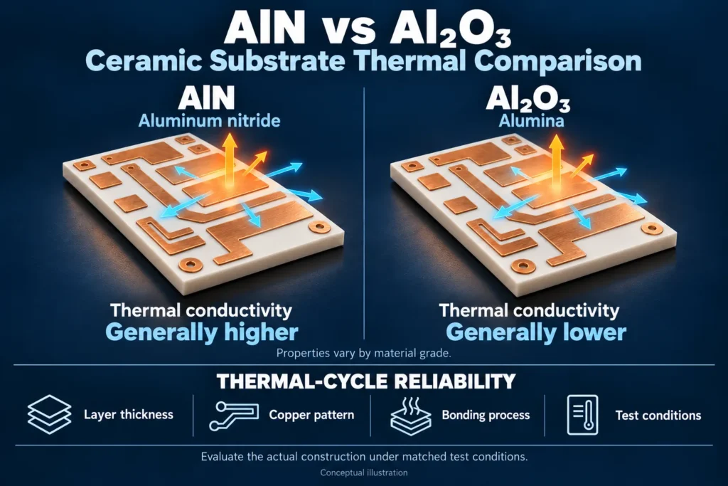
AlN generally offers higher thermal conductivity than alumina. It can help move heat away from a concentrated source. CeramTec’s substrate comparison also shows differences in CTE and mechanical properties between its material grades.
These properties are inputs to a reliability assessment, not a universal ranking. Better heat conduction does not automatically mean better resistance to thermal cycling. Copper thickness, ceramic thickness, pattern geometry, and the metal-to-ceramic bond also influence the result.
Direct bonded copper (DBC), active metal brazed (AMB), and thin-film constructions should not be treated as identical. Delamination in a metal-ceramic structure refers to separation at an interface. It does not imply the board contains the same organic bonding layers as an FR-4 stack.
For an AlN substrate reliability comparison, keep the relevant construction and test conditions aligned. Compare actual reports for the proposed materials. Avoid choosing a substrate from a headline conductivity value or a cycle count from a different structure.
Both AlN and Al2O3 can use the same categories of testing. The application and failure mechanisms determine the profile and acceptance criteria.
How Reliability Testing Data Supports Application Selection
Start with the expected use conditions: operating temperatures, temperature changes, electrical stress, mounting, and cooling. Then identify the failure mechanisms that matter. Our ceramic PCB applications guide provides context for different applications.
For a power application, ask whether the tested construction represents the planned heat path and insulation requirements. For an RF application, thermal and insulation reports still matter, but they do not establish RF loss or impedance performance. Those need their own validation.
A useful report should make the evidence traceable. Review:
- Part number, drawing revision, material grade, construction, and sample identification.
- Sample quantity, lot information, and whether specimens represent the ordered design.
- Test method and revision, actual conditions, and any deviations.
- Baseline and final measurements, inspection images, and the acceptance criteria.
- Failures, their timing, and any investigation or corrective action.
- Test laboratory, date, equipment identification, and calibration status.
Keep three types of evidence separate. Typical material data describe a material. Qualification results evaluate a defined design or construction. Lot records describe checks linked to a production batch. None automatically substitutes for the others.
Consider two reports listing the same cycle count. One uses an unmetalized coupon; the other uses a patterned board. They answer different questions. Even two patterned-board reports need comparable profiles, sample sizes, and inspection methods.
Do not convert laboratory cycles directly into years of service. A lifetime estimate needs a validated relationship to the intended operating conditions. Review that relationship with the responsible reliability engineer.
FAQ
What is thermal cycling testing for ceramic PCBs?
It repeatedly exposes specified samples to a temperature profile, then checks for defined physical or electrical changes. The report should state temperatures, transitions, dwell conditions, cycle count, sample construction, and acceptance criteria.
Is AlN more reliable than Al2O3 under thermal stress?
Not necessarily. AlN usually conducts heat better, but thermal-stress performance also depends on the metal pattern, thicknesses, bonding process, mounting, and test conditions. Compare evidence for the actual proposed construction.
What is dielectric withstand testing checking for?
It checks whether a specified insulation path meets the required withstand criteria during an applied voltage test. It is not a direct measure of service life or proof that every physical defect is absent.
Can Benlida provide reliability test reports with ceramic PCB orders?
Ask Benlida to confirm which reports are available for the selected construction and order. Agree on the required tests, sample scope, acceptance criteria, and documentation before ordering. Do not assume all reliability tests are included by default.
Need Reliability Data for a Power or RF Application?
Explore Benlida’s ceramic PCB manufacturing options and discuss your project’s requirements. Request ceramic PCB reliability data for the proposed construction, with report availability and test scope confirmed before order release.
Share the drawing revision, material preference, ceramic and metal thicknesses, quantity, operating conditions, and required acceptance criteria. Identify whether you need material data, design qualification evidence, or order-specific records.