Ceramic PCB Applications — LED, Power Electronics & RF Circuits
Ceramic PCB applications include high-power LED modules, power converters, radio-frequency (RF) and microwave circuits, and selected automotive electronics. Ceramic substrates can combine electrical insulation with useful thermal or high-frequency properties. Their value depends on the material, circuit structure, and operating conditions.
Not every hot or high-frequency circuit needs ceramic. Start with the constraint you need to solve: heat flow, electrical isolation, signal loss, or repeated temperature changes. Then compare complete designs, not material names alone.
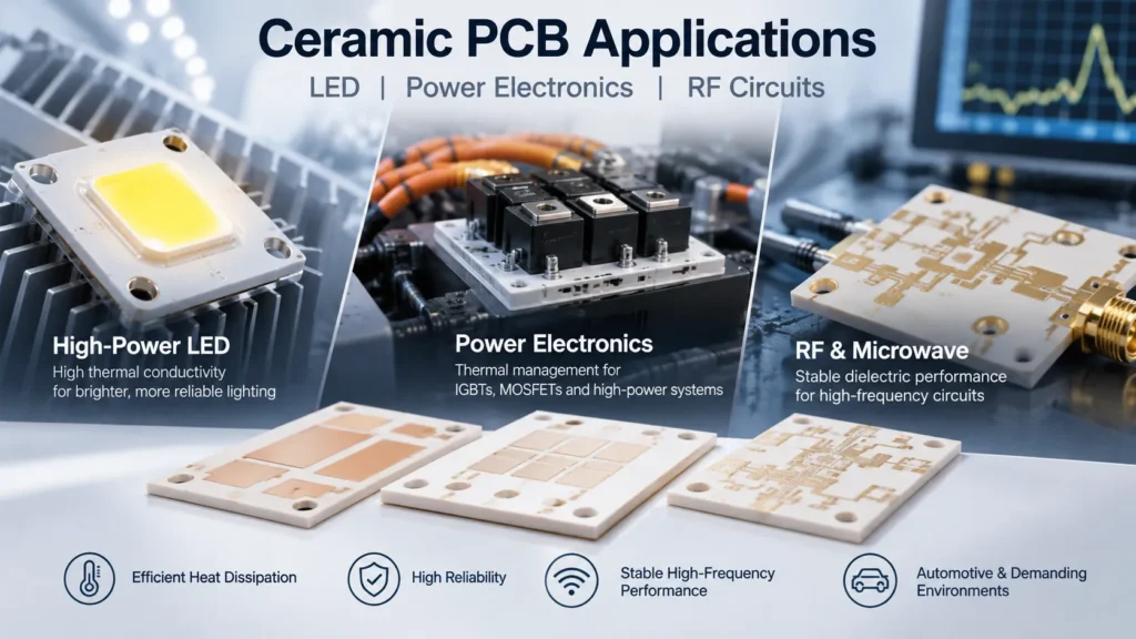
Where Is Ceramic PCB Used?
A ceramic PCB carries conductive circuits on or within a ceramic substrate. In industry, the term covers several constructions. A small substrate inside an LED package differs from a copper-clad power substrate or a multilayer RF module.
Material choice also matters. Alumina, or aluminum oxide, is a common ceramic substrate material. Aluminum nitride is often considered when heat transfer is a priority. Silicon nitride can be useful where mechanical toughness and thermal cycling are important. Kyocera’s ceramic packaging material guide illustrates these different roles.
Applications range from concentrated LED heat sources to electrically isolated power switches and compact RF filters. However, a material selected for one role may not suit another. For example, a ceramic chosen for RF integration may offer very different thermal properties from aluminum nitride.
Define what you are buying: a bare circuit substrate, a semiconductor package, or an assembled module. That distinction changes the drawings, connections, and tests required.
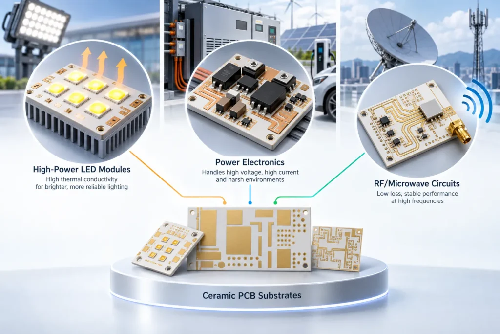
High-Power LED Applications
Ceramic can be useful in compact LED arrays and lighting modules that concentrate heat in a small area. The objective is to control the LED junction temperature while maintaining the required electrical isolation.
A conventional aluminum metal-core PCB has a copper circuit layer, an insulating dielectric, and a metal base. Aluminum spreads heat, but the dielectric can limit heat flow through the board. Cree LED’s PCB thermal design guide demonstrates this limitation in its MCPCB example.
A suitable ceramic structure may reduce this part of the thermal resistance. It does not automatically outperform every aluminum board. Dielectric thickness, copper layout, heat-source area, and mounting conditions all affect the comparison.
Also distinguish the LED package from its host board. Ceramic substrates used in LED packages help transfer heat away from the device. That package may still be mounted on a metal-core PCB.
For the complete module, follow the heat path through the package, attachment layer, board, thermal interface, and heat sink. Improving the substrate alone cannot fix poor heat-sink contact or inadequate cooling.
If an aluminum design meets the temperature and lifetime requirements, ceramic may not justify a change. Review the practical alternatives in our guide to aluminum PCB for LED projects before changing the stackup.
Power Electronics Applications
Power electronics use ceramic substrates in some IGBT and MOSFET modules, motor drives, inverters, and converters. Here, the substrate must move heat toward the cooling system while insulating live conductors from the baseplate or cooler.
Power modules often use direct-bonded copper, or DBC, and active-metal-brazed, or AMB, substrates. These processes join copper to ceramic. They are different from the laminated construction of a conventional FR-4 PCB.
The choice is not simply “ceramic or no ceramic.” Rogers’ metallized ceramic substrate range includes alumina, aluminum nitride, and silicon nitride options for different thermal and mechanical priorities. Its listed applications include power inverters, electric motors, and renewable-energy converters.
The surrounding module still needs careful design. Copper geometry, ceramic thickness, attachment materials, and mechanical support affect performance. Changes in temperature create expansion differences between materials, which can stress their interfaces.
Ask which part of the system needs ceramic. A module may use a ceramic power substrate while its gate-driver or control board uses FR-4. Selecting an IGBT, MOSFET, or silicon carbide device does not automatically require every board around it to be ceramic.
RF and Microwave Applications
Ceramic substrates are used in RF packages, filters, antenna modules, and selected microwave circuits. Here, the main requirement may be controlled electrical behavior or compact integration, rather than maximum heat transfer.
Thin-film circuits and low-temperature co-fired ceramic, or LTCC, modules are examples of different approaches. LTCC can integrate conductors and circuit features within a multilayer ceramic structure. It is not the same process as a DBC power substrate.
Kyocera’s LTCC millimeter-wave data shows antenna and filter applications. It also lists different dielectric constants and losses for different grades and frequencies. This is why “ceramic” alone is not a useful RF specification.
Check dielectric constant, or Dk, which affects impedance and electrical dimensions. Check dissipation factor, or Df, which describes dielectric loss. Use values measured under relevant conditions. Conductor properties, trace geometry, and transitions into connectors or packages also contribute to RF performance.
Compare the proposed ceramic structure with suitable RF laminates. Ceramic-filled organic laminates are not the same as solid ceramic substrates. Our high frequency PCB design guide covers the wider layout and material decisions. Validate the finished circuit across its operating frequency band.
Automotive and High-Temperature Applications
Automotive uses include selected power modules in traction inverters, onboard chargers, and power converters. Ceramic can help combine heat transfer and electrical isolation in these assemblies. Its suitability depends on the actual vehicle location and duty cycle.
Do not assign every under-hood circuit the same temperature requirement. Separate ambient temperature, substrate or case temperature, and semiconductor junction temperature. The peak inside a switching device is not the temperature of every nearby board.
Repeated heating and cooling also matter. Infineon’s discussion of power-module reliability explains how these changes stress die attachment, bond connections, substrates, and other package interfaces.
Define the mission profile: temperatures, dwell times, load changes, and expected service life. Then assess thermal cycling, power cycling, vibration, humidity, and insulation requirements as appropriate. A substrate that transfers heat well can still fail if its connections or mounting are unsuitable.
Ceramic material selection alone does not establish automotive qualification. The supplied substrate and assembled product need evidence against the customer’s requirements. A general claim of high temperature resistance is not enough.
How to Determine If Your Application Needs Ceramic PCB
Consider ceramic when an existing design cannot meet a documented thermal, electrical, or mechanical requirement. First check whether layout, cooling, or a different conventional stackup can resolve the issue. Our ceramic PCB vs FR-4 comparison provides additional material-selection context.
Consider a hypothetical LED module that exceeds its junction-temperature target. If measurements identify the board’s insulation layer as the bottleneck, compare a ceramic option under the same load and cooling conditions. If the main problem is poor contact with the heat sink, improve that interface first. The diagnosis should guide the material decision.
Prepare these inputs before requesting a recommendation:
- Heat and cooling: Power dissipated as heat, hotspot locations, contact area, cooling method, and permitted temperatures.
- Electrical conditions: Working voltage, isolation needs, current paths, and required insulation tests.
- RF requirements: Operating band, impedance, acceptable loss, and critical dimensional tolerances, where relevant.
- Mechanical and thermal loads: Board dimensions, mounting method, temperature range, cycling, vibration, and enclosure constraints.
- Assembly details: Device packages, attachment method, surface finish, connection method, and any rework restrictions.
Ask suppliers to identify the material grade and manufacturing process in their proposals. Compare equivalent structures, quantities, inspection requirements, and acceptance criteria. A lower bare-substrate price may not produce the lowest assembled cost.
Use matching revisions for circuit artwork, fabrication notes, and assembly documents. Ask each supplier to state any proposed changes. This makes quotes easier to compare and prevents a substitution from silently changing the agreed design.
Prototype the full heat path or RF circuit, not just an isolated material sample. Measure the temperatures or electrical performance that drove the selection. Agree on reliability testing and acceptable results before production.
When discussing a project with a ceramic PCB manufacturer, confirm which materials and processes are feasible for that design. Do not assume that every supplier offers every ceramic technology described here.
FAQ
Why is ceramic PCB used for high-power LED instead of aluminum PCB?
Ceramic may be selected when a metal-core board’s insulating layer limits heat transfer within the available space. It can provide another path to electrical isolation and heat removal. However, aluminum PCB remains suitable for many LED projects. Compare junction temperature, the complete cooling path, assembly needs, and cost before choosing.
What power electronics applications require ceramic PCB?
Some IGBT and MOSFET power modules, inverters, and converters use ceramic substrates to combine insulation with heat transfer. No application name alone makes ceramic mandatory. Selection depends on power density, voltage isolation, cooling, cycling requirements, and module construction. Control circuitry may still use a conventional PCB.
Can ceramic PCB handle RF and microwave frequencies?
Yes, suitable ceramic materials and circuit processes can support RF and microwave applications. Specify the material grade, frequency band, dielectric properties, conductor system, and geometry. Different ceramics have different losses and thermal properties. Validate the actual circuit rather than treating all ceramic substrates as equivalent.
What operating temperature can ceramic PCB withstand?
There is no universal maximum operating temperature for ceramic PCB. The finished structure’s rating depends on the ceramic, metallization, attachment materials, components, and connections. Specify continuous and short-duration conditions separately. A ceramic firing temperature, a reflow peak, or a semiconductor junction rating is not a board operating limit.
Discuss Your Ceramic PCB Application with Benlida
Share your circuit artwork or Gerber files, fabrication drawing, dimensions, material preference, and quantity. Include thermal, electrical, assembly, and testing requirements. For an assembled module, add the BOM and assembly drawing.
and ask Benlida to confirm the proposed material, process, and project scope before ordering.

