

High Frequency PCB Materials Comparison — Rogers vs Taconic vs Isola
What Are High-Frequency PCB Materials?
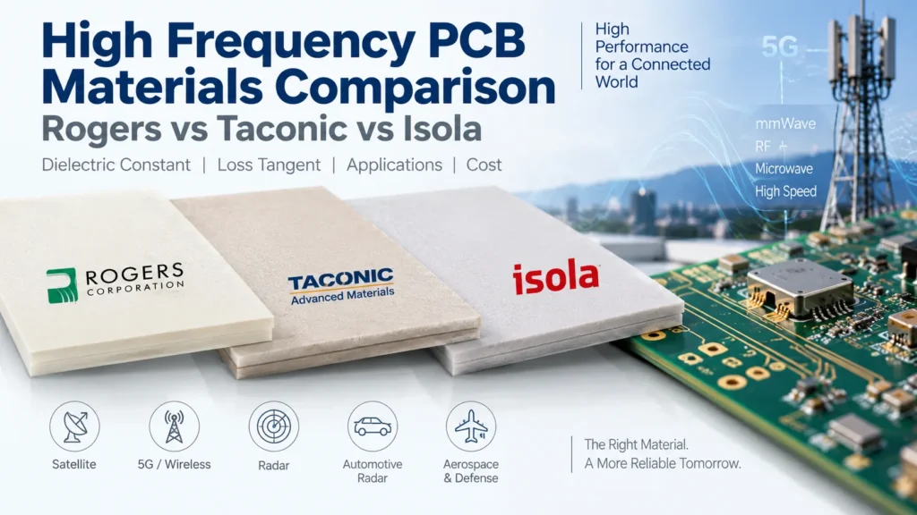
High-frequency PCB materials are laminates selected for controlled dielectric properties and low signal loss in RF and microwave circuits. Rogers, Taconic, and Isola offer different material families. Compare specific grades by dielectric constant, loss tangent, construction, and fabrication needs. Choose a material that meets the circuit’s performance requirements at an acceptable total board cost.
Dielectric constant, or Dk, affects signal propagation, impedance, and the size of structures such as antennas. Loss tangent, also called dissipation factor or Df, describes dielectric loss. A lower Df can reduce that part of the loss, but it does not describe the complete signal path.
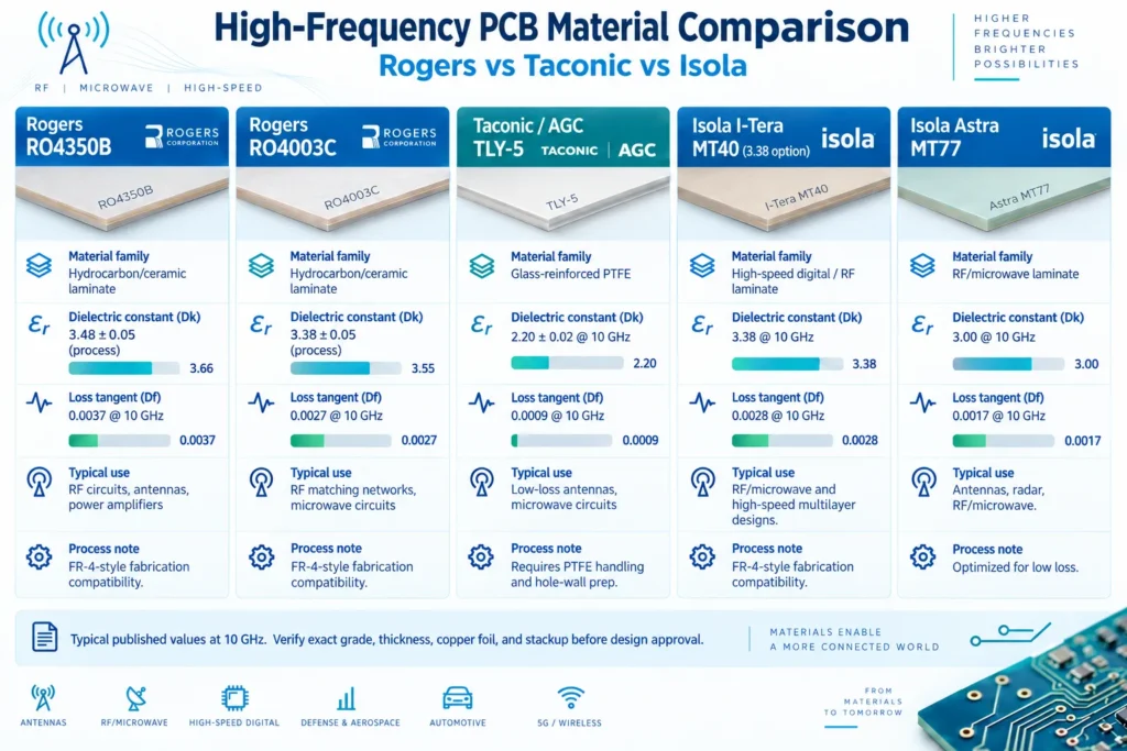
This RF laminate comparison uses five examples: Rogers RO4350B and RO4003C, Taconic TLY-5, and Isola I-Tera MT40 (RF/MW) and Astra MT77. The figures help create a shortlist. They are not a guarantee of finished PCB performance or a reason to substitute materials without redesign checks.
Rogers Laminates — RO4350B, RO4003C Overview
RO4350B and RO4003C are reinforced hydrocarbon/ceramic laminates, not PTFE materials. They support RF and microwave designs while using FR-4-type fabrication processes. That processing compatibility can simplify a manufacturing review, but the fabricator still needs to approve the stackup and process details.
The Rogers RO4000 data sheet provides separate process Dk and design Dk values. Process Dk is tied to the material test. Design Dk supports circuit modeling under different conditions. Treating them as interchangeable can cause an impedance or phase error.
RO4003C has a lower published Df than RO4350B at 10 GHz. However, loss is not the only selection criterion. Rogers states that RO4003C is not UL 94 V-0 rated, while standard RO4350B meets that flame-rating requirement. Verify the exact construction; RO4350B LoPro does not share the standard material’s UL designation. A laminate rating also does not certify a complete product.
For a closer look at one grade, read our Rogers RO4350B PCB material guide. Do not carry a previous design’s trace widths into a different laminate without recalculating the stackup.
Taconic PTFE-Based Materials
TLY-5 is a useful Taconic-family example of a glass-reinforced PTFE laminate. The current AGC TLY-5 data sheet lists applications such as antennas, satellite communications, and radar. Its published low-Dk, low-Df combination makes it a candidate when dielectric loss is a tight constraint.
The tradeoff includes manufacturing requirements. AGC’s TLY-5 processing guide describes handling precautions and PTFE hole-wall preparation before plating. Confirm that the fabricator can process the proposed construction. A low-loss material does not compensate for poor hole quality or dimensional control.
Do not assume that every Taconic grade behaves like TLY-5, or that a Taconic board will always cost less than a Rogers board. Ask for the exact grade, thickness, copper foil, and quantity. Then compare the complete fabrication quotes, including any special processing and testing.
Isola High-Speed Digital Laminates
Isola serves high-speed digital applications, but its range is not limited to digital boards. The I-Tera MT40 (RF/MW) data sheet explicitly covers both high-speed digital and RF/microwave designs. It also describes FR-4 process compatibility and the availability of laminate and prepreg.
Astra MT77 is another RF/microwave option, with manufacturer-listed antenna and radar applications. Its published Df is lower than the I-Tera option shown below. This does not make it the automatic choice for every circuit.
For a mixed RF and digital board, examine the complete stackup. A core is a cured laminate; prepreg bonds layers during lamination. Confirm the properties and thicknesses of both. Do not apply one core’s headline Dk to every dielectric layer.
High-speed digital selection also depends on edge rate and channel length, not just clock frequency. Keep the RF operating band and digital channel requirements separate when asking for a material recommendation.
Dielectric Constant and Loss Tangent Comparison
The table summarizes manufacturer-published values at 10 GHz. Rogers design Dk is listed separately because its stated frequency range is 8–40 GHz. These are not results from one controlled comparison. Test methods and material constructions differ, and typical values are not finished-board acceptance limits.
RF Material Comparison
| Brand/Material | Dielectric Constant | Loss Tangent | Typical Use | Relative Cost |
|---|---|---|---|---|
| Rogers RO4350B | Process: 3.48 ± 0.05*; design: 3.66 | 0.0037 at 10 GHz | RF circuits, antennas, power amplifiers | RFQ-dependent |
| Rogers RO4003C | Process: 3.38 ± 0.05; design: 3.55 | 0.0027 at 10 GHz | RF matching networks and microwave circuits | RFQ-dependent |
| Taconic / AGC TLY-5 | 2.20 ± 0.02 at 10 GHz | 0.0009 at 10 GHz | Low-loss antennas and microwave circuits | RFQ-dependent |
| Isola I-Tera MT40 (RF/MW), 3.38 option | 3.38 at 10 GHz | 0.0028 at 10 GHz | RF/microwave and high-speed multilayer designs | RFQ-dependent |
| Isola Astra MT77 | 3.00 at 10 GHz | 0.0017 at 10 GHz | RF/microwave antennas and radar | RFQ-dependent |
Read the test conditions: Rogers process Dk and Df use 10 GHz at 23°C and IPC-TM-650 2.5.5.5; process Dk uses clamped stripline. Design Dk uses the differential phase length method over 8–40 GHz. TLY-5 lists method 2.5.5.5 for both values. The Isola sheets list 2.5.5.5 for Dk and Bereskin Stripline for Df.
*The RO4350B 4 mil version has a process Dk of 3.33 ± 0.05. TLY-5 can be supplied with other Dk choices. The I-Tera row covers only the 3.38 RF/MW option. Confirm the ordered thickness, foil, construction, and applicable design data before using any number in a simulation.
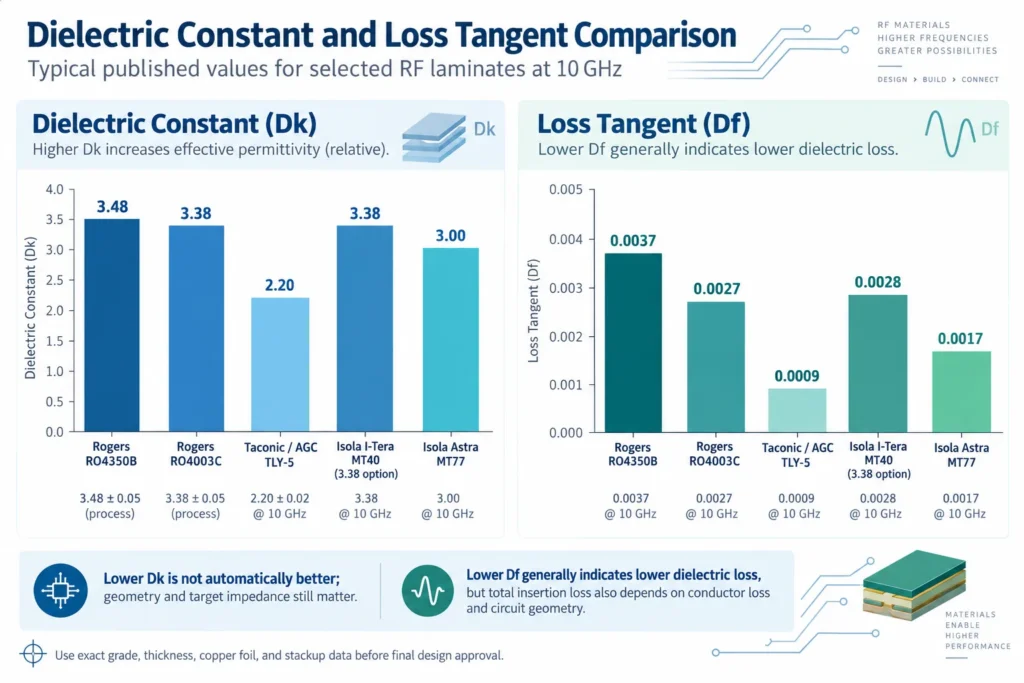
Lower Dk is not automatically better. It changes the geometry needed for the intended impedance or resonance. Rogers explains why Dk depends on test conditions, including frequency and temperature. Select a consistent material model rather than choosing the smallest number.
Likewise, Df is not insertion loss in decibels. Conductor loss and circuit geometry also matter. The Rogers mmWave design guide shows how copper roughness affects loss and propagation. Comparing Df alone can miss an important difference between two finished boards.
The cost column is deliberately quote-dependent. Without matched specifications and current quotes, a fixed Rogers–Taconic–Isola price ranking would be misleading.
Choosing the Right Material by Frequency Range and Budget
Begin with the circuit’s requirements, then eliminate unsuitable candidates. There is no universal frequency at which every FR-4 board must change to one named RF laminate. A short connection and a long antenna feed can have different loss budgets at the same frequency.
- Define the operating conditions. State the RF band, bandwidth, path length, power, temperature range, and allowed loss. For digital channels, include the interface requirements and edge rates.
- Select suitable electrical data. Ask for Dk and Df information relevant to the operating band and construction. A 10 GHz table is a starting point, not proof of performance at millimeter-wave frequencies.
- Confirm the buildable stackup. Agree on core and prepreg thicknesses, copper foil, impedance targets, and tolerances. Check the effect of a material change on traces, antennas, and matching structures.
- Compare equivalent quotations. Use the same board dimensions, layer count, quantity, finish, and inspection requirements. Identify whether material availability, panel utilization, special processing, or test work changes the price.
- Validate before volume production. Agree on suitable impedance and RF measurements for the prototype. Define test structures, measurement conditions, and pass/fail limits with the engineering team.
At higher microwave and millimeter-wave frequencies, request data beyond the headline Dk/Df pair. Copper roughness, dielectric thickness variation, and transitions can become important to the performance margin. Do not approve a replacement solely because two data sheets show similar nominal values.
A hybrid stackup may use RF material only where needed and another approved material elsewhere. This can reduce laminate expense, but it adds compatibility questions. The fabricator must assess bonding, thermal expansion, registration, and reliability. It is not an automatic cost saving.
Record the approved material and stackup revision in the fabrication package. If purchasing proposes an alternative, ask what changes electrically and mechanically. Update the model and validation plan where needed. Keep the approval tied to the exact grade and construction, not a broad instruction such as “Rogers or equivalent.” This gives engineering and purchasing the same acceptance criteria.
Use our high frequency PCB design guide for layout considerations. For the manufacturing discussion, review high frequency PCB manufacturing and request confirmation of the exact material and process route. Approve substitutions in writing after engineering review.
FAQ
What is the difference between Rogers and Taconic materials?
Compare grades, not just brands. RO4350B and RO4003C use hydrocarbon/ceramic systems, while TLY-5 uses glass-reinforced PTFE. Their electrical properties and processing needs differ. These examples do not represent every material either supplier offers.
Which high-frequency laminate has the lowest loss tangent?
Among the examples listed here, TLY-5 has the lowest published 10 GHz Df, at 0.0009. The figures use different test methods and are not a universal ranking. Check the exact construction and measure total circuit loss before deciding.
Is Isola material suitable for RF applications?
Some Isola grades are explicitly intended for RF and microwave use. I-Tera MT40 (RF/MW) and Astra MT77 are examples. Suitability still depends on the operating band, loss budget, stackup, environment, and manufacturing process. Do not treat all Isola materials as interchangeable.
Does material choice affect PCB manufacturing cost significantly?
It can affect both laminate cost and fabrication work. Thickness, foil, panel size, availability, processing, and test requirements all influence the quote. Compare the total cost of boards meeting the same requirements, rather than assuming one brand is always cheaper.
Choosing a Laminate for Your RF Design?
Send the target frequency range, loss budget, board dimensions, quantity, and proposed stackup. Include Gerber or ODB++ files, drill data, impedance requirements, and fabrication notes when available. If the layout is still open, share the requirements and candidate grades first.
Request an RF material consultation with Benlida to discuss availability and manufacturability for your project. Ask for confirmation of the exact laminate, foil, thickness, test scope, and any proposed alternatives before releasing the design.