

PCB Gerber File Guide — What to Include and Common Mistakes
What Is a Gerber File
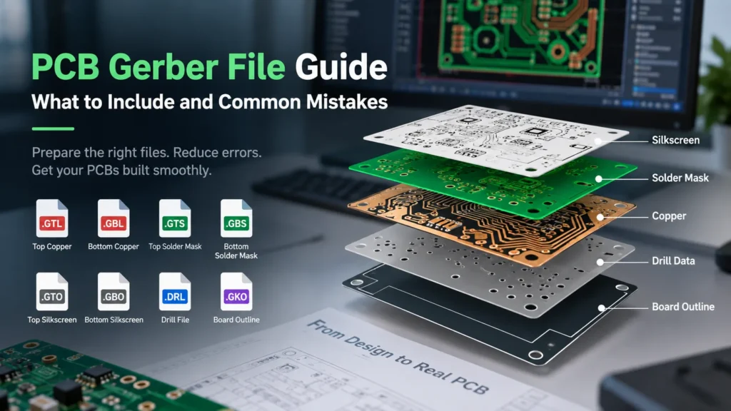
A complete PCB Gerber file package includes every copper layer, the required solder mask and silkscreen layers, a board outline, and drill data. Gerber X2 adds information about the layers and features. Drill data often comes in separate NC or Excellon files. Manufacturing notes complete the package.
A Gerber file describes a production layer using precise shapes and coordinates. It is not a screenshot or a complete PCB design project. As Ucamco explains the Gerber format, the format can represent copper, mask, legend, and drill or route data.
The practical question is whether the manufacturer can identify every file and build the intended board without guessing. File count alone cannot answer that. A two-layer board and a multilayer board with blind vias need different packages.
Required Layers in a Gerber File Package
Export each required production layer separately. Include the physical board boundary and all hole information. The table lists common naming examples. File extensions are not universal requirements: readable names, correct file content, and the agreed layer map matter more.
| Layer | File Extension | Purpose |
|---|---|---|
| Top copper | .gbr or .GTL | Defines top-side traces, pads, and copper areas. |
| Bottom copper | .gbr or .GBL | Defines bottom-side copper when present. |
| Each inner copper layer | .gbr or CAD-specific suffix | Defines each internal signal or plane layer in a multilayer board. |
| Top solder mask | .gbr or .GTS | Defines the intended top-side mask openings. |
| Bottom solder mask | .gbr or .GBS | Defines bottom-side mask openings when required. |
| Top silkscreen or legend | .gbr or .GTO | Defines top-side printed markings when specified. |
| Bottom silkscreen or legend | .gbr or .GBO | Defines bottom-side printed markings when specified. |
| Board outline and cutouts | .gbr or .GKO | Defines the finished board boundary and internal cutouts. |
| Plated hole data | .drl or .txt for some NC exports; .gbr for Gerber | Defines plated holes, with drill spans identified where needed. |
| Non-plated hole and slot data | .drl, .txt, or .gbr, depending on output | Defines non-plated features and their geometry. |
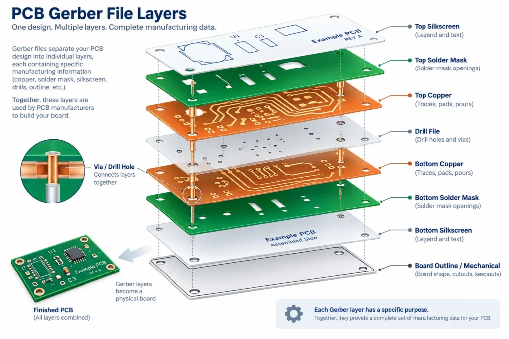
Check the actual export format before sending it. A familiar suffix does not prove that a file contains the expected data. Do not create empty silkscreen files simply to match a checklist. State clearly when a layer or finish is intentionally absent.
Add a fabrication drawing or specification covering material, thickness, copper requirements, surface finish, tolerances, and any controlled impedance. Provide the layer order from top to bottom. A Gerber Job file can also carry machine-readable fabrication details where the workflow supports it.
Solder paste layers serve stencil preparation. They are not required for every bare-board order. For an assembly order, add the BOM, placement data, and assembly instructions. The PCB BOM preparation guide explains the component information needed alongside the PCB fabrication files.
Gerber X2 vs RS-274X Format
In export dialogs, RS-274X often refers to Extended Gerber without X2 attributes. Strictly speaking, X2 is also Extended Gerber. The difference is extra information, not a different drawing of the board.
Ucamco’s X2 explanation describes attributes that identify file function, polarity, and pad function. These can tell CAM software that a file represents bottom copper or that a feature is a via pad. The image remains unchanged.
A compliant older Gerber reader can read the image while ignoring the attributes. It may not use the additional information. Prefer X2 when your design software supports it, and confirm the manufacturer’s submission requirements. Avoid obsolete Standard Gerber, also called RS-274D.
X2 does not correct a missing layer, outdated drawing, or wrong drill export. Keep filenames, attributes, and the fabrication drawing consistent. Renaming a file does not change its internal layer function.
Drill File Requirements
NC means numerical control. Excellon-style NC files are a common way to transfer hole locations and tool sizes. Gerber can also describe drilling and routing. Ask which format the manufacturer accepts instead of assuming every supplier uses the same import settings.
Provide machine-readable drill data, not just a PDF drill map. Ucamco’s XNC specification explains why clear coordinate and tool definitions matter in drill-data exchange. Review these items before sending the package:
- Units and coordinate interpretation are unambiguous.
- Hole positions align with the copper pads using the same origin.
- Plated and non-plated holes are clearly distinguished, preferably in separate files.
- Blind and buried holes identify their start and end layers.
- Slots include their full shape, dimensions, and plating requirement.
- Finished hole requirements and tolerances appear in the fabrication notes.
Do not enlarge design holes yourself to compensate for plating unless the manufacturer has specifically agreed that workflow. Manufacturing compensation belongs in the agreed CAM process. Check that mounting holes and slots remain present after export.
Common Gerber File Mistakes
Missing files and mixed revisions
A package may contain both outer copper layers but omit an inner plane, mask layer, or drill file. Re-export the complete set after the final design change. Put it in a clean folder and remove superseded outputs before creating the ZIP.
Use one board identifier and revision across the ZIP, drawing, and file list. If the design changes after submission, send a clearly identified replacement package. Ask the manufacturer to confirm which revision will enter production.
Wrong units or misaligned data
A preview can look plausible while the dimensions are wrong. Measure the outline in the exported data. Overlay drills with copper and check several holes across the board, not only one corner. Keep all layers at 1:1 scale.
Do not manually mirror bottom layers. The Gerber layer specification calls for aligned data in a common coordinate system. It also requires an accurate, closed board profile. A drawing with dimensions does not replace that machine-readable outline.
Unclear layer order or conflicting instructions
Name internal layers in physical sequence. Check that filenames, X2 attributes, and the stackup agree. Keep solder mask and solder paste outputs distinct. Include cutouts in the correct profile data rather than leaving them only on a drawing.
A viewer check can reveal missing or misplaced data. It does not confirm that every feature is manufacturable. Use the PCB DFM checklist for the separate review of design rules, fabrication requirements, and unresolved engineering questions.
How to Export Gerber Files from Common PCB Design Software
Start with a saved, checked design and updated copper fills. Menu labels vary by software release. Export into a clean revision folder and inspect the generated files, even when you reuse a saved output job.
KiCad
Open the PCB Editor’s Gerber Plot dialog from the File menu. Select the required copper, mask, silkscreen, and Edge.Cuts layers. Plot the files, then use Generate Drill Files. Keep its origin consistent with the Gerber export. The KiCad PCB Editor documentation covers both outputs and supports separate plated and non-plated drill files.
Altium Designer
Generate Gerber or Gerber X2 files through Fabrication Outputs. Add NC Drill as a separate output. Check units, resolution, and origin in both configurations. For repeat work, save the outputs in an Output Job. Altium’s fabrication-data guidance explains these settings. Direct menu exports and Output Jobs retain separate configurations.
Autodesk Fusion Electronics
Open the 2D PCB and launch the CAM Processor from Manufacturing. Choose a CAM job suited to the board’s layer count. Review the Gerber sections and confirm that Excellon drill output is included. Process the job and inspect its outputs. Follow Autodesk’s manufacturing-data workflow for the available export options.
Finally, open the exported layers and drills together in an independent viewer. Check the outline, cutouts, layer count, hole alignment, mask openings, and markings. Review the fabrication notes against the files. ZIP only the approved revision and include a short file list.
FAQ
What layers must be included in a Gerber file package?
Include every copper layer, the specified solder mask and silkscreen layers, the board outline, and all required drill or route data. The exact set depends on the design. Add fabrication notes and the layer stackup. Assembly orders need additional component and placement information.
What is the difference between Gerber X2 and RS-274X?
X2 adds attributes to Extended Gerber, historically called RS-274X. Those attributes identify features such as layer and pad function. They do not change the image. X2 remains compatible with compliant readers that do not use the attributes.
What drill file format do PCB manufacturers require?
Excellon-style NC drill files are a common choice, but requirements vary. Some workflows accept Gerber drill data. Confirm the format, units, origin, plated-hole identification, and slot handling before export. A drill map alone is not a substitute.
What is the most common Gerber file mistake first-time buyers make?
There is no universal ranking. A major mistake to check first is an incomplete package, especially missing drill data or inner copper layers. Compare the exported file list with the design, then review the exact ZIP you will submit.
Prepare your PCB files for review
For Benlida’s PCB manufacturing services, send the Gerber package, drill data, fabrication drawing, revision, quantity, and required delivery date. Flag any unresolved stackup or tolerance questions so they can be addressed before production.