

PCB Prototype to Production — How to Scale Up Successfully
What Changes Between Prototype and Production?
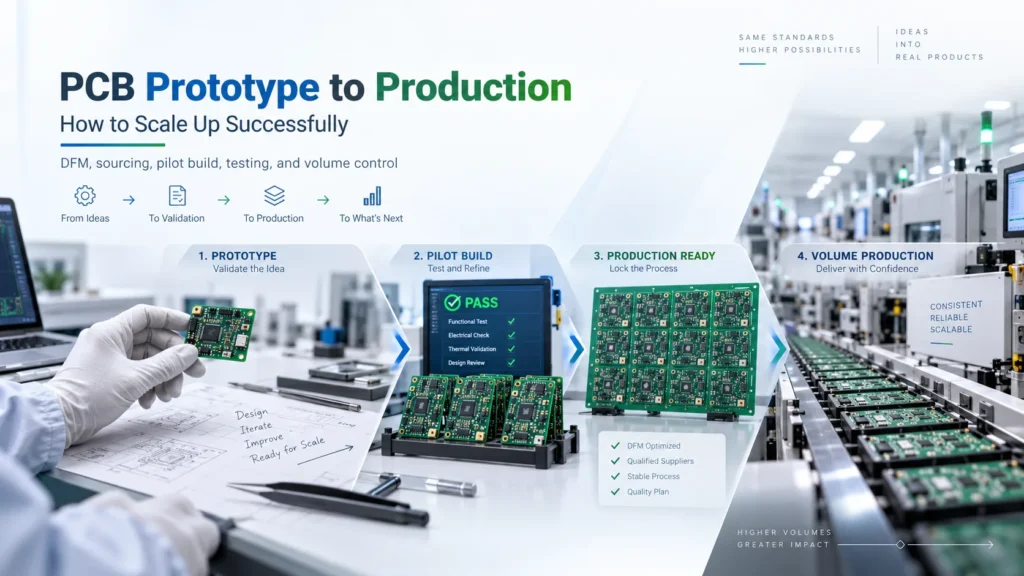
Moving a PCB prototype to production requires more than ordering additional boards. Recheck the design against the planned manufacturing process. Confirm materials, component supply, tooling, and test coverage. Then use a production-representative pilot build to resolve problems before increasing quantities. Higher volume does not automatically justify less inspection.
A prototype shows how a particular build performs. Production must deliver consistent results across repeated builds. A circuit that worked after manual adjustment may still need design or process changes.
This guide covers bare-board fabrication and, where components are installed, PCBA assembly. Component sourcing, placement, firmware, and functional testing apply to the assembly scope. They should not be confused with manufacturing and electrically testing a bare PCB.
Use this checklist to identify what needs confirmation. Both stages require controlled files and suitable quality checks; the emphasis changes as production becomes repeatable.
Prototype vs Production Checklist
| Factor | Prototype Stage | Production Stage |
|---|---|---|
| Design release | Track the build revision and engineering changes | Approve a complete release package and control later changes |
| DFM review | Check feasibility and record build issues | Close findings for the intended materials, process, and supplier |
| Component supply | Obtain approved parts for validation | Confirm approved part numbers, quantities, and delivery dates |
| Tooling and panels | Assess handling, assembly, and test needs | Validate repeatable panels, fixtures, and program revisions |
| Quality plan | Check function, investigate failures, and review coverage | Maintain required tests and use approved sampling where appropriate |
| Build approval | Review design results and unresolved risks | Review pilot evidence, corrective actions, and capacity before release |
DFM Revalidation Before Volume Orders
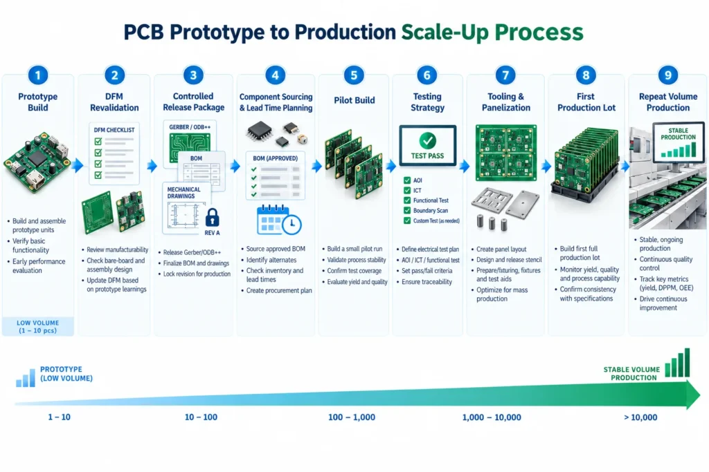
Design for manufacturability, or DFM, asks whether the design fits the process that will make it. Revalidate it when moving from prototype to volume manufacturing. This matters especially if the supplier, materials, panel, assembly method, or design revision changes.
Start with one controlled release package. Altium’s design-release documentation separates source, fabrication, and assembly data and preserves a revision snapshot. The practical lesson is simple: do not combine Gerbers from one revision with a BOM or drawing from another.
For the bare board, review the stack-up, material requirements, copper thickness, drill structure, clearances, surface finish, and specified tolerances. Check any prototype deviations that the fabricator accepted. A one-off workaround is not automatically suitable for repeated production.
For an assembly, review component footprints, polarity, placement access, soldering conditions, and inspection access. Check design for testability as well. Test points, connectors, and firmware access must support the agreed production test.
For example, a prototype connector may be hand soldered. The production route may use selective soldering instead. That change calls for a fresh review of tool access and heat exposure.
Record each finding, its owner, and its resolution. Update the affected files together. Approve any remaining deviation explicitly before the next build. The release should identify what changed and which checks confirmed the change.
Component Sourcing Lock-In and Lead Time Planning
For PCBA projects, sourcing lock-in means an approved BOM and controlled substitutions. It does not mean refusing all alternatives. Qualifying suitable alternatives before a shortage can reduce the need for rushed engineering decisions.
Specify the manufacturer and complete orderable part number. Include the package, value, tolerance, rating, and approved alternatives where relevant. A description such as “10 kΩ resistor” is not enough to control all important characteristics.
Check lifecycle status as well as stock. TI’s product lifecycle definitions distinguish active parts from those not recommended for new designs or entering last-time-buy status. A part available for a prototype may still create a repeat-order risk.
Assign someone to monitor manufacturer notices. TI’s product change notification guidance covers changes that can affect fit, form, function, quality, or reliability. Review affected parts and qualification information before deciding whether your product needs further checks.
Agree who purchases each item, who approves alternatives, and who owns unused inventory. Our cost guide compares turnkey vs partial PCB assembly, including the effect of sourcing responsibilities.
Build the schedule around confirmed requirements. Include component arrival, tooling readiness, fabrication, assembly, testing, and release approval. Some activities can overlap, but an unresolved critical item can hold up the build.
Distinguish the first production lot from repeat orders. Setup and qualification work may make the first lot take longer. Repeat orders still depend on materials and available capacity. Confirm whether quoted days are calendar or working days and whether shipping is included. Our PCB lead time guide explains the planning factors.
Testing Strategy Changes at Volume
Production testing should become repeatable and efficient without losing required coverage. Do not assume that every prototype needs full inspection or that every production lot should use sampling.
Separate three decisions: what characteristics matter, how to check them, and how many units to check. Bare-board electrical testing, optical inspection, in-circuit testing, and functional testing answer different questions.
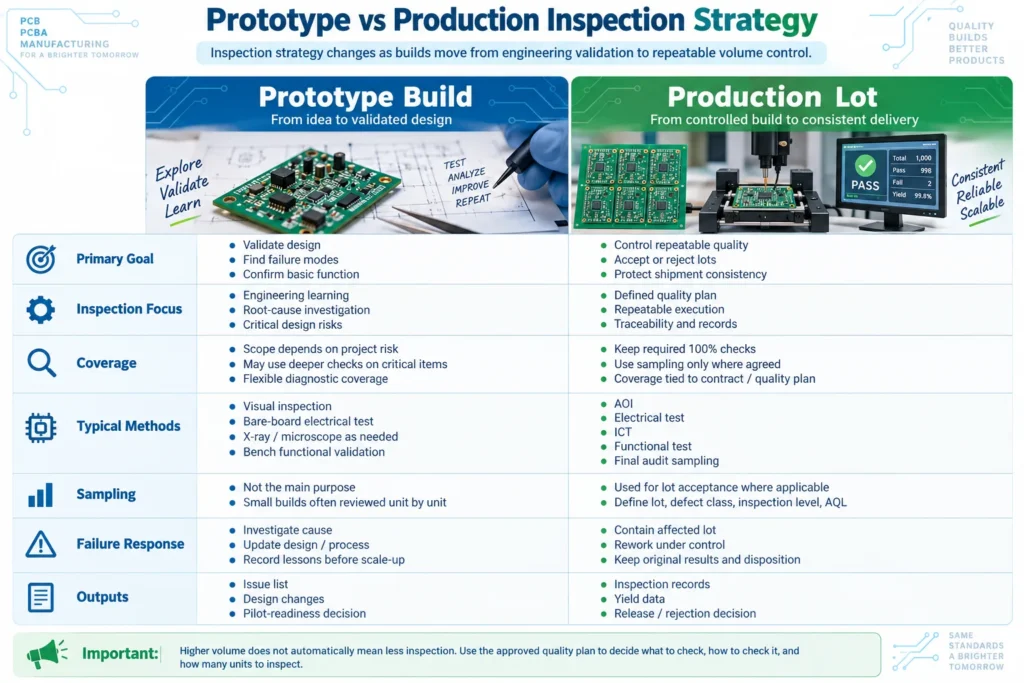
NIST’s acceptance-sampling guidance explains that sampling supports a decision to accept or reject a lot. It does not prove that every unit is defect-free or measure the lot’s exact quality level.
Where sampling is appropriate, agree on the lot definition, defect categories, inspection level, AQL, and acceptance rules. Select the sample randomly under that plan. AQL means Acceptance Quality Limit. ISO 2859-1 provides an AQL-based framework with switching rules. Use the agreed edition and actual scheme requirements, not an improvised sample size.
Keep any every-unit electrical or functional tests required by the contract, product requirements, or approved quality plan. An all-unit functional test can coexist with a sampled final audit. One does not automatically replace the other.
Higher volume may justify dedicated test fixtures. Confirm access, fault coverage, program revision, and test limits first. Keysight’s ICT guidance notes that in-circuit testing may need complementary inspection or functional testing.
Define the response to failed boards or rejected lots, including investigation, containment, rework, and authorized retesting. Keep original results. See our guide to PCB assembly inspection levels for a closer look at coverage and acceptance.
Tooling and Panelization Considerations at Scale
Panelization groups boards for manufacturing and assembly. A layout that saves laminate area may still be awkward to handle, inspect, test, or separate. Review the panel with both the fabricator and assembler.
Altium’s panelization guidance treats panel size, spacing, borders, and board separation as coordinated decisions. Confirm machine compatibility, support, alignment marks, tooling holes, and access around components.
Review depanelization before approving the layout. Components close to a separation line may need more clearance or a different separation method. Validate the planned panel and handling method on a representative build.
Non-recurring engineering, or NRE, refers to project-specific setup and development work. PCB or PCBA quotes may separate engineering charges from tooling costs. Assembly-related items may include stencils, fixtures, and test programming. The exact scope depends on the supplier and project.
Ask which charges recur, what can be reused, and what a design change would invalidate. Also agree on tooling ownership, storage, maintenance, and replacement. A lower unit price can hide a different setup or testing scope.
Include test-cycle time and handling in the capacity discussion. A fast placement process does not establish the output of the whole line. The slowest required operation may limit the number of completed, accepted assemblies.
Common Mistakes When Scaling Too Fast
A rushed production release can repeat a small build problem across a larger order. Watch for these mistakes:
- Releasing a prototype that only worked after undocumented wire changes, component swaps, or manual adjustment.
- Changing suppliers, materials, or assembly methods without reviewing the effect on the design and test plan.
- Ordering the full volume before checking critical material availability and approving the pilot results.
- Treating repaired units as first-pass successes and losing visibility of recurring defects.
- Changing inspection coverage without documented approval or a defined response to failures.
Run the pilot with the intended production files, material choices, tooling, and test method wherever practical. Record any differences from the planned route. Decide whether those differences leave important questions unanswered.
Review first-pass results, defect patterns, retest results, rework, and actual cycle times. Look across the run, not only at the final number of working boards. NIST’s process-stability guidance distinguishes a stable process from isolated acceptable results. One successful pilot does not guarantee long-term capability.
Set project-specific release criteria before the pilot. Assign responsibility for approving the next quantity increase. If recurring failures remain unexplained, investigate them before expanding the build.
FAQ
Does my design need re-review before scaling to production?
Yes. Recheck the released revision against the intended supplier, materials, tooling, assembly route, and test plan. Resolve prototype workarounds and review any changes. The scope should reflect the project’s risks.
How much does lead time change from prototype to production?
There is no fixed increase. The first production lot may need additional sourcing, tooling, or qualification work. Repeat orders depend on material availability, capacity, and testing. Confirm the schedule and its starting conditions.
Should I keep 100% inspection at production volume?
Keep every-unit checks where the contract, product requirements, or approved quality plan requires them. Use sampling only for the checks covered by an agreed plan. A larger order alone does not justify reduced inspection.
What causes yield drops when scaling PCB production?
Possible causes include unresolved design margins, material changes, process variation, tooling problems, and test issues. Compare failure data with what changed between builds. Do not assume there is one universal cause.
Ready to Move from Prototype to Production?
Discuss the next build with Benlida before increasing quantities. For projects with components, review our PCB assembly services and request confirmation of the proposed manufacturing and test scope.
Send the current Gerber or ODB++ package, drill data, fabrication drawing, revision, quantities, and delivery requirements. For PCBA, add the BOM, pick-and-place file, assembly drawing, firmware, and test requirements as applicable.
Include prototype findings, known deviations, sourcing responsibilities, and proposed pilot acceptance criteria. Ask Benlida to confirm the review scope, open questions, tooling needs, and schedule in writing.