

Flexible PCB Materials — Polyimide vs PET vs LCP
Flexible PCB Material Options
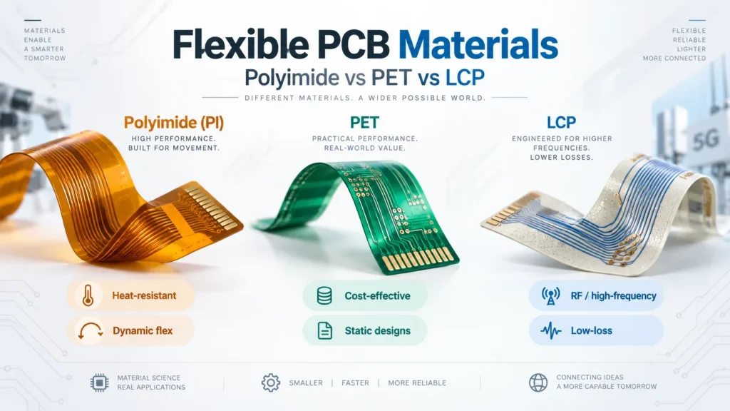
Polyimide is a common starting point when a flexible circuit needs heat resistance and repeated movement. PET can reduce material cost in suitable static, lower-temperature designs. LCP is worth evaluating when high-frequency loss and moisture stability matter. None guarantees a reliable circuit by itself.
This FPC materials comparison focuses on three substrate families: polyimide (PI), polyethylene terephthalate (PET), and liquid crystal polymer (LCP). These are important options, not a complete list of flexible PCB substrate types.
A substrate film is only one part of a flexible printed circuit, or FPC. Copper, bonding layers, protective coverlay, and local stiffeners also affect performance. An adhesive-based laminate and an adhesiveless laminate can behave differently despite using the same base polymer.
Start with the application. Will the circuit fold once during installation or move throughout its life? What assembly temperatures will it see? Does it carry low-speed control signals or an RF signal with a strict loss budget?
Polyimide — Properties and Best Applications
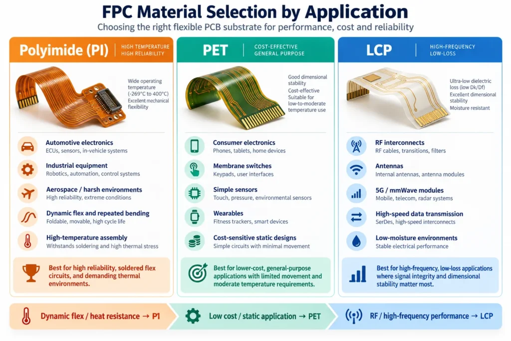
Polyimide is a practical candidate for circuits that need solder assembly, compact routing, or repeated bending. Typical design situations include moving interconnects and flex sections between rigid circuit areas. Suitability still depends on the selected laminate and finished construction.
Qnity’s Pyralux material range includes copper-clad laminates, coverlays, bonding films, and adhesives. Its AP family uses an adhesiveless, all-polyimide construction. This illustrates why “polyimide” alone is not a complete purchasing specification.
For a PI design, specify the dielectric thickness, copper grade and thickness, bonding system, and coverlay. Ask the fabricator to review the full stack-up before freezing the drawing. Two quotations labeled “PI flex” may describe different constructions.
PI does not automatically deliver the longest flex life. A thick multilayer circuit can place more strain on its conductors than a thinner construction at the same bend radius. Copper fatigue may determine the service life before the substrate film fails.
PI also remains relevant to RF designs. Some grades target low-loss performance. Compare the actual dielectric data and circuit requirements before assuming that every high-frequency design needs LCP.
PET — Where Lower Cost Makes Sense
PET is worth considering for cost-sensitive circuits with limited heat exposure and modest movement requirements. Examples include membrane switches, printed sensor circuits, and fixed interconnects. It is not a drop-in replacement for PI in an unchanged manufacturing process.
Mylar Specialty Films’ flexible-electronics brochure describes polyester films for copper laminates, overlays, and membrane-switch circuitry. Its heat-stabilized PET grades address dimensional changes during processing. The brochure also identifies Melinex ST507 for FPC applications using low-temperature solder reflow.
That does not make every PET film compatible with soldering. Confirm the exact grade, adhesive, conductor system, and time-temperature profile. Indium’s low-temperature soldering guidance identifies heat-sensitive flex circuitry as one application. The joint still needs its own reliability assessment.
Also distinguish printed conductive-ink circuits from etched copper circuits. Both can use flexible films, but their electrical, connection, and manufacturing requirements differ.
Consider a keypad tail that is bent during installation and then remains fixed. PET may be a useful candidate if its connection method and temperature limits fit. If the same tail passes through a moving hinge, the requirements change. Do not carry the static material decision into the moving design without testing.
Lower film cost does not guarantee a lower finished-part price. Special handling, attachment methods, yield, and qualification work can change the result. Compare equivalent finished constructions, quantities, and inspection requirements when reviewing quotes.
LCP — High-Frequency and RF Flex Applications
LCP flex circuit material is a candidate for RF interconnects, antenna structures, and high-speed signal paths. Its appeal is not simply that it bends. Selected grades combine low dielectric loss with low moisture uptake.
Kuraray’s LCP film data highlights high-frequency electrical behavior and stability under moisture exposure. These properties can help when humidity-related changes would disturb an RF design. They do not prove the performance of an entire assembled circuit.
Discuss conductor roughness, bonding layers, controlled-impedance dimensions, and connector transitions alongside the base film. A low-loss substrate cannot compensate for every layout or connection problem. Dynamic bending also needs separate validation.
Check the supply status of the exact copper-clad laminate, not just the polymer family. In its FCCL business announcement, Kuraray announced plans to end Vecstar copper-clad laminate production by the end of June 2026. The notice separately stated that LCP film production and sales would continue. Film availability and laminate availability are different questions.
For procurement, request the manufacturer, grade, thickness options, and substitution rules. Confirm availability for both prototypes and repeat orders. Treat a proposed alternative as a material change that needs review, not an automatic equivalent.
Thermal Resistance and Flex Life Comparison
Thermal resistance here means tolerance to heat exposure, not the ability to conduct heat away. Separate brief assembly exposure from continuous operating temperature. A short solder-heat test does not establish a long-term service rating.
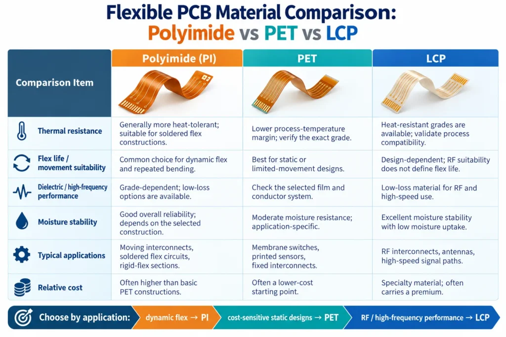
The table is a screening guide, not a specification or a Benlida price list. Comparisons assume an otherwise suitable design. Exact grades, construction, quantities, and purchasing conditions can change the outcome.
FPC Material Comparison
| Material | Thermal Resistance | Flex Life | Dielectric Performance | Relative Cost |
|---|---|---|---|---|
| Polyimide (PI) | Generally more heat-tolerant than standard PET; full stack-up limits apply | Common dynamic-flex candidate; copper and construction determine life | Grade-dependent; low-loss options are available | Often higher than basic PET constructions |
| PET | Lower process-temperature margin; heat-stabilized grades need specific profiles | Often screened for static or limited-movement use; qualify actual duty | Check the selected film and conductor system at the operating frequency | Often a lower-cost starting point |
| LCP | Heat-resistant grades available; validate lamination and assembly conditions | Design-dependent; RF suitability does not establish dynamic life | Selected grades offer low loss and low moisture uptake | Specialty grades may carry a premium; confirm the complete quote |
Minco’s flex-circuit introduction distinguishes static installation bends from dynamic, repeated movement. This distinction belongs in the specification before choosing a material.
For moving circuits, define the bend radius, direction, travel, cycle count, and operating environment. Test the finished construction under representative conditions. A substrate film test alone cannot establish the life of plated copper, bonded layers, and assembled connections.
Define failure criteria before the test. These may include intermittent opens during motion, an agreed resistance change, or visible cracking and separation. Record the fixture geometry and motion speed so later builds can repeat the test. A continuity check after bending can miss brief interruptions during motion.
Copper foil matters too. JX Advanced Metals’ HA and HA-V2 foil guidance connects bending behavior with copper grain structure and orientation. Specify the actual foil grade and construction instead of relying on a broad material label.
Use our FPC bend radius design guide to develop the geometry requirements. Material selection and bend design should be reviewed together.
Dielectric Performance at High Frequency
Dielectric constant, or Dk, affects signal propagation and impedance. Dissipation factor, or Df, describes dielectric loss. Neither number should be compared without its test conditions.
For example, Panasonic’s R-F705S LCP datasheet lists typical Dk values of 2.9 at 14 GHz and 3.3 at 10 GHz. The first uses a balanced circular disk resonator method; the second uses a cavity resonator method. Both list a typical Df of 0.002.
These are not guaranteed values or interchangeable inputs. Frequency and test method both differ. Ask which data is appropriate for the intended stack-up and simulation.
Compare candidate grades at relevant frequencies, with matched methods and moisture conditioning where possible. Include thickness tolerances and bonding layers. Do not select a material solely because one brochure lists a smaller Dk.
Total circuit loss also includes conductor and radiation losses. Rogers’ transmission-line guidance explains how copper roughness can increase conductor loss at high frequency. Verify the complete signal path against the design’s loss budget.
For a broader high frequency PCB materials comparison, our RF design guide also covers stack-up and layout considerations.
FAQ
Is polyimide better than PET for flexible circuits?
PI is often the stronger candidate for demanding assembly heat and repeated motion. PET may be more economical for suitable static, lower-temperature designs. Compare the complete construction rather than the polymer name alone.
When should I use LCP instead of polyimide?
Evaluate LCP when dielectric loss and moisture stability are important to the RF design. Compare specific LCP and PI grades under relevant conditions. Confirm fabrication compatibility, supply, and finished-circuit performance.
Does material choice affect FPC bend radius?
Yes, but thickness, copper, bonding layers, and static or dynamic use also matter. Agree on the stack-up and bend conditions together. Validate the finished circuit for the required movement.
Which flex material is most cost-effective for static applications?
PET is often a cost-effective starting point when temperature and connection requirements allow it. PI may offer better overall value if PET requires extra process changes. Compare total finished-part cost.
Choosing the Right FPC Substrate?
Start your FPC material selection with the operating conditions, not a preferred resin name. Review Benlida’s FPC manufacturing services, then send the requirements for project-specific discussion.
Include Gerber or ODB++ files, a fabrication drawing, quantities, and revision. Add the proposed stack-up, copper thickness, bend geometry, and static or dynamic duty. State operating temperatures, assembly conditions, and any impedance or RF loss targets.
If component assembly is needed, also provide the BOM, placement files, and connection or test requirements. Ask Benlida to confirm the proposed material grade, manufacturing route, availability, and lead time before placing the order.