FPC vs Rigid PCB — Comparison Guide for Choosing the Right Technology
FPC vs rigid PCB is mainly a decision about movement, available space, component support, and total product cost. Choose a rigid board when the circuit needs a stable platform and no intentional bending. Consider FPC when the circuit must fit a three-dimensional space or connect moving sections.
Neither technology is automatically cheaper, denser, or more reliable. A flexible circuit can simplify connections, but it also needs controlled handling and a suitable mechanical design. Start with the product requirements, then compare complete, buildable solutions.
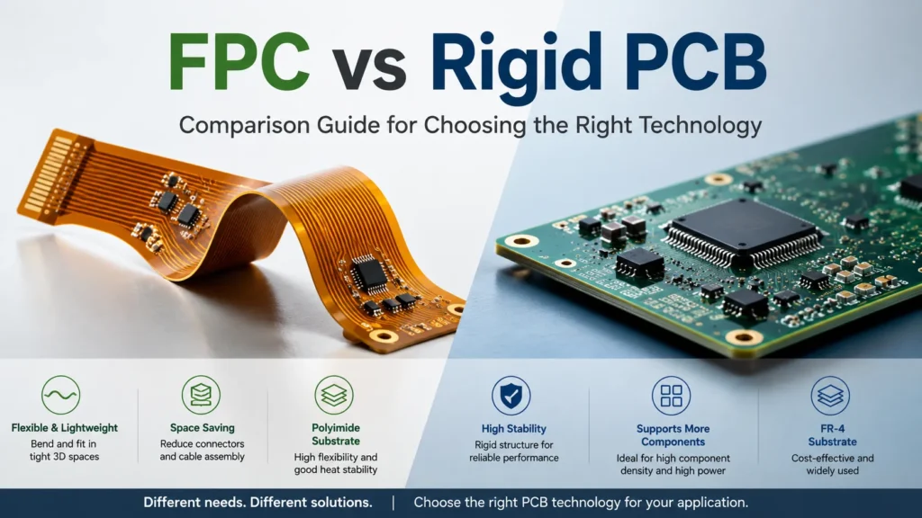
FPC vs Rigid PCB — Key Differences
FPC means flexible printed circuit. It is a type of PCB, not a separate category outside printed circuit boards. The main distinction is whether the circuit structure is designed to bend.
The table below compares typical project considerations. It does not set universal limits for either technology.
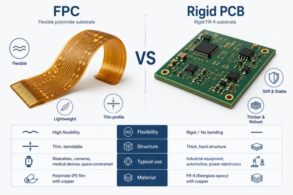
| Selection Factor | FPC | Rigid PCB |
|---|---|---|
| Cost | Fabrication may cost more for a comparable simple circuit. Savings may come from fewer cables, connectors, or installation steps. | Often economical for standard, fixed layouts. Include any separate interconnects and their assembly costs. |
| Flexibility | Can fit curved spaces or support designed motion. Static and dynamic applications need different design reviews. | Provides a fixed platform. It is not intended for repeated bending during use. |
| Component Density | Dense layouts are possible in supported areas. Bend zones, routing, and assembly access constrain usable space. | Provides stable support for dense layouts. Achievable density still depends on stackup, routing, packages, and manufacturing rules. |
| Assembly Complexity | May reduce final wiring work. Component assembly can require carriers, stiffeners, and controlled handling. | Conventional board handling is often straightforward. Separate boards and cables can add final assembly work. |
| Best Applications | Compact three-dimensional layouts, lightweight interconnects, and properly engineered moving connections. | Fixed controllers, supported component platforms, and products with straightforward mounting space. |
Do not treat this comparison as a scorecard with one winner. Identify the constraint that a standard rigid layout cannot satisfy. Then check whether flex solves it without creating a larger production or reliability problem.
When to Choose FPC
FPC is worth evaluating when board shape and connection routing limit the product. A thin circuit may pass around a housing feature or connect two sections at different angles. It may also replace several wires with a defined connection pattern.
For a weight-sensitive product, compare the complete interconnect arrangement. Include wires, connectors, support parts, and the circuit itself. Replacing a cable harness may reduce mass, but additional shielding or stiffeners can offset that benefit.
Start by separating installation bends from operating motion. A circuit folded into place during assembly has a different duty from one moving with a hinge. Specify which condition applies before choosing the layer stack.
Polyimide is common, but it is not the only flexible substrate. For example, Panasonic’s FELIOS materials include polyimide and liquid crystal polymer options. Material selection must also consider electrical performance, temperature, processing, and the intended movement.
Mark component areas separately from bend areas. Small components do not automatically make an unsupported location suitable for solder joints. Connector insertion forces and the weight of mounted parts also need support.
Before committing to FPC, give the FPC manufacturer a mechanical drawing showing the installed shape. Include bend locations, mounting points, expected movement, and component support. A flat outline alone cannot explain the full requirement.
When to Choose Rigid PCB
A rigid board is a practical starting point when components stay in one position and the enclosure provides enough space. It offers a stable surface for assembly, connectors, test access, and mounting hardware.
This is useful for a fixed control board or a replaceable module. It also avoids adding flex-specific processing when the product gains little from bending.
FR-4 is common, but “rigid PCB” does not specify one material. The Rogers RO4000 data sheet describes rigid hydrocarbon/ceramic laminates, illustrating another material family. Select the actual laminate for the electrical and environmental requirements.
Rigid construction alone does not guarantee cooling, vibration resistance, or high component density. Those results depend on the complete design. When discussing rigid PCB manufacturing, provide the stackup, material requirements, mounting constraints, and test requirements rather than requesting only a board type.
Cost Comparison: FPC vs Rigid PCB
Compare two costs separately: the fabricated circuit and the finished product. A lower bare-board price does not always produce the cheaper assembled system.
Flex quotes can be affected by material construction, layer count, coverlay openings, stiffeners, panel utilization, and handling requirements. Rigid designs also become more costly with demanding materials, dense interconnects, tight tolerances, or special processes.
For a fair comparison, request quotes for the same quantity, revision, inspection scope, and delivery assumptions. Ask each supplier to separate one-time tooling from recurring unit costs.
Then include the parts and work around the board:
- Cables, connectors, fasteners, and support parts.
- Component assembly, handling fixtures, and final installation.
- Programming, inspection, electrical testing, and functional testing.
- Expected rework, replacement access, and service requirements.
This approach follows the distinction between board cost and system cost in Würth Elektronik’s flex design guide. Removing a connector can save parts and labor. It can also make one damaged section harder to replace.
Use measured assembly time and supplier quotations where possible. Until those inputs exist, any claimed saving is an estimate. Do not apply a fixed FPC price multiplier or assume rigid-flex will always reduce total cost.
Reliability Comparison
Reliability depends on the failure risks in the actual product. A rigid board avoids an intentional flexing zone. An FPC can remove some wired connections, but it introduces bend and handling conditions that need control.
Minco’s flexible-circuit introduction distinguishes static installation from dynamic flexing. Repeated movement can fatigue conductors. A circuit that survives installation is not automatically qualified for repeated motion.
For a moving flex section, define the bend shape, motion range, cycle target, operating temperature, and nearby mechanical restraints. Check the full stackup, not just the base film. Copper, insulating layers, and local reinforcement all affect bending behavior.
Keep components, solder joints, and vias out of the intended bend zone. Avoid sharp creases and uncontrolled twisting. For more layout context, see the FPC bend radius design rules. Confirm the allowed geometry with the fabricator for the specific construction; no single radius or cycle count applies to every FPC.
On a rigid board, review mounting loads, connector forces, temperature changes, and solder-joint stress. Mechanical stiffness is useful, but it does not make the assembly immune to vibration or thermal fatigue.
Validate prototypes in their installed form. For dynamic flex, monitor electrical continuity during representative motion, not only before and after a flat-board test. For either technology, define acceptance criteria and the environmental tests the product actually needs.
Rigid-Flex as a Hybrid Option
A rigid-flex PCB combines rigid component regions and flexible interconnect regions in one integrated board structure. It is not simply two rigid boards joined with a removable flex cable.
Consider rigid-flex PCB when dense, supported component sections must connect across a constrained three-dimensional layout. It may remove connectors and reduce connection steps. However, fabrication, assembly planning, and repair can become more demanding.
A stiffener bonded beneath an FPC provides local mechanical support. That feature alone does not make the circuit an integrated rigid-flex design.
Compare three realistic arrangements before choosing: one rigid board, separate boards with an FPC interconnect, and an integrated rigid-flex board. Draw the installed shape for each. Count connection points, identify replaceable sections, and agree on a test plan. Choose the arrangement that satisfies the requirements with acceptable production and service costs.
Make the Choice with a Project Checklist
Record the reason for choosing a technology before freezing the design. A useful selection review answers these questions:
- Packaging: Which enclosure dimension or connection path rules out a simple rigid layout?
- Motion: Does the circuit bend during installation, during service, or repeatedly during operation?
- Support: How will mounted components and connector loads be supported?
- Production: Do the compared quotes include equivalent assembly and testing work?
- Service: Can the likely failed section be replaced without discarding the entire assembly?
If an answer is uncertain, turn it into a drawing requirement, quotation question, or prototype test. Resolve those gaps before treating the architecture as final.
FAQ
Is FPC more expensive than rigid PCB?
It often costs more to fabricate than a comparable simple rigid circuit, but this is not universal. Materials, layers, geometry, quantity, and inspection affect the quotation. FPC may lower finished-product cost if it removes enough wiring, connectors, or installation work. Compare equivalent, fully costed designs.
Can FPC handle the same component density as rigid PCB?
FPC can support dense circuitry, but the answer depends on the construction and assembly process. Component regions need suitable support, while bend regions need placement restrictions. Evaluate routing, package footprints, coverlay openings, and assembly access. Do not assume the flexible label alone determines density.
What applications require FPC instead of rigid PCB?
FPC is useful when the circuit itself must follow a tight three-dimensional path or provide a designed moving connection. Compact sensor assemblies and hinged connections are examples. However, an application name does not make FPC mandatory. Compare it with a rigid board and suitable cable arrangement.
Is rigid-flex PCB a better option than choosing FPC or rigid alone?
Sometimes. Rigid-flex can combine supported component areas with integrated flexible connections. It is valuable when that integration solves a packaging or connection problem. Separate boards may remain easier to source, replace, or service. Compare manufacturability, validation needs, and complete product cost before deciding.
Discuss the Right Circuit Structure for Your Project
Share the installed dimensions, connection layout, movement requirements, quantity, and target operating environment with Benlida. For a developed design, include Gerber or ODB++ files, drill data, stackup, and fabrication drawings. Add the BOM, placement data, and assembly or test requirements if you need PCBA.
If the architecture is still open, provide a mechanical sketch and your main constraints. Use the review to identify what must be confirmed before selecting flexible, rigid, or rigid-flex construction.

